Table of Contents
Construction Phase II
On the January, 25th we had a local prototype presentation. In a feedback round we identified two major problems regarding my first prototype of the insole
- inconstant values
- no reliable values (10 kg close to the wires brought different values than 10 kg far away from the point of measurement)
Therefore I decided to recreate the sole itself. In exchange with my mentor Fiore Basile I took a look into a prior fabricademy presentation from the student Sam Calish

[Photo taken from Sam Calish´s documentation]
It is an analog pressure sensor. The two sides you can see in the picture are the main components for one sole. If you put both sides together and cover the “pads” with semi conductive material current will only flow if weight presses both sides of the sole together.
According the sketch I created my own sketch in Rhino and cut cooper foil with our vinyl cutter.
28.02.2018 l Experimental Session
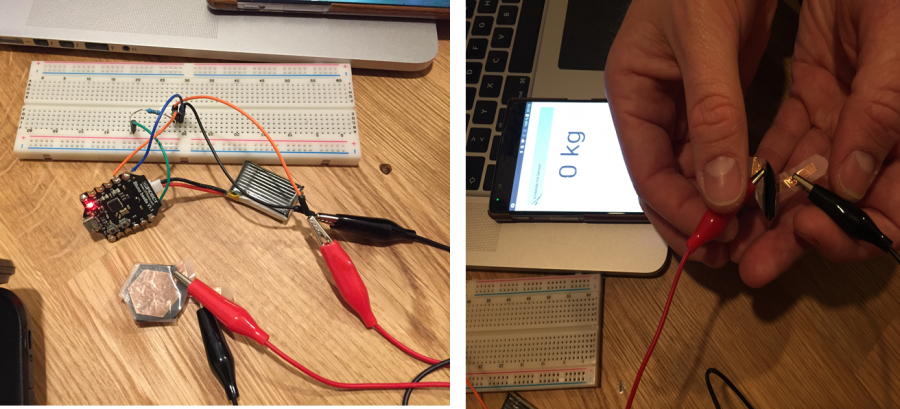
I met a friend of mine who wrote a mobile application for my analog pressure insole. He wrote the app in React native with the extension of the BLE manager. We used a Beetle BLE an Arduino Uno based board with Bluetooth 4.0 (BLE) . It is said that it is probably the smallest Arduino BLE board in the market. In our case is the Beetle the peripheral and the app is the master. The peripheral offers different services which can be determined by programming. We needed the status notify which enables a permanent connection if the Bluetooth is on. For the source of energy we used 3,7 V Battery and connected the wires like a normal analog pressure sensor. We tested in step 1 the sandwich out of cooper foil, semi conductive material Econflex and another layer of cooper foil.
The results were good. And we started to test step 2:
Like you can see in Sam´s example created 10 fields and connected those with wires. Consequently every wire needs a pin and the readings of each field have to be summed up. We tested how this summarizing of data could look like in the app if we have two data sources which means 2 pins are occupied.
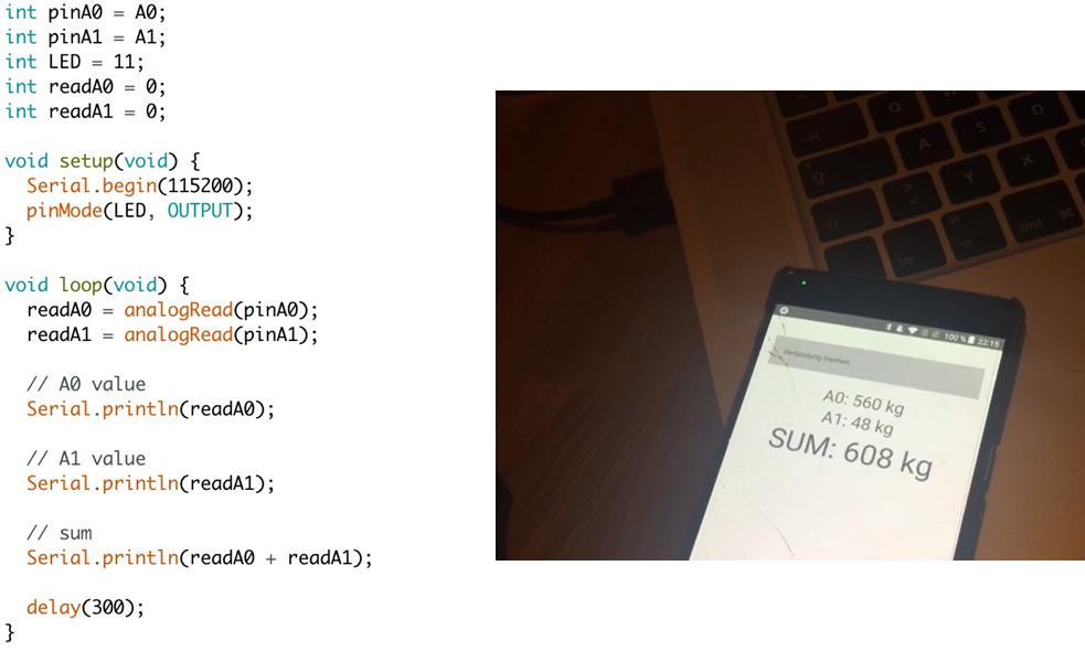
See the result in the following clip
We were satisfied and noticed that the values are better (broader) if we are using semi-conductive foam instead of Econflex that is why I will go on experimenting with the foam.
Next Steps:
To manage the readings of the pads efficiently I have to decrease the numbers of the pads we determined at max. 10 pads which means I need 10 pins. We thought about to use an Arduino Nano and additional Bluetooth board.
10.03.2018 l FabLab Session
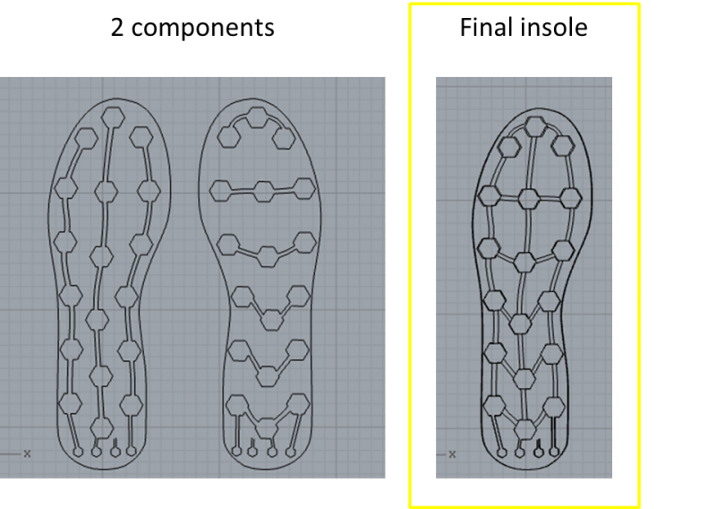
Like mentioned above I did a new sketch in Rhino with less pads
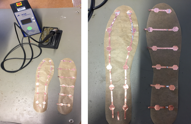
I decided to extend the endings of the lines to have some space where I can solder the wires. The next step was to cut the pads and the lines out of cooper foil with the vinyl cutter. I was a bit tricky because we only have cooper tape and the stripes did not have the exact width of my sketch. I had to paste two strips side by side to cover the full sketch.
One side of the cooper tape is adhesive, I could easily past it on baking paper. I chose baking paper because it deals with max. heat of 300° degrees, therefore I am able to solder on it.
It was really important that both components match perfectly. Therefore I made a negative template out of normal paper and fixed it on the sole out of baking paper. Due to the template I knew exactly where I had to paste the elements of cooper foil.

I would recommend to use a cooper foil in DIN A4 to avoid the soldering. I had to solder the parts which where not cut out of one strip to ensure the conductivity of my sketch.
21.03.2018 l FabLab Session
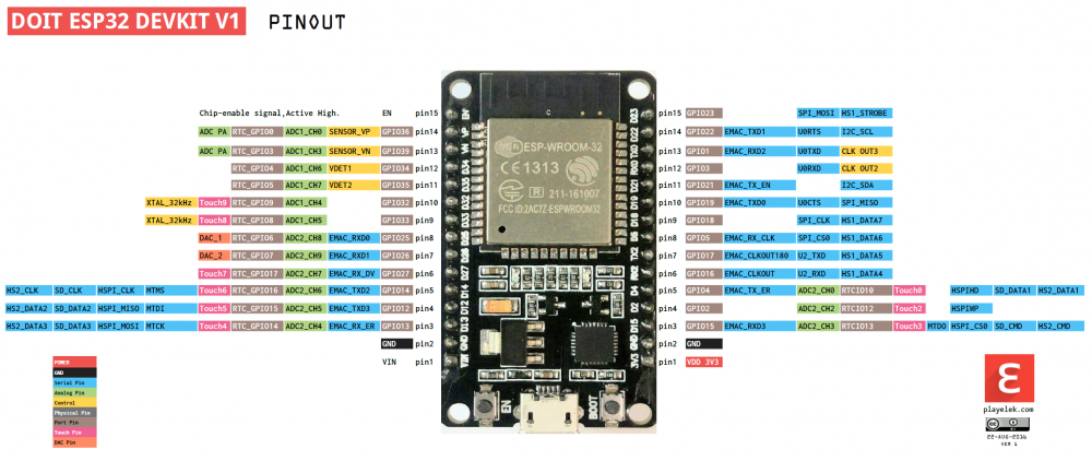
I discussed my challange with the microcontroller and the Bluetooth module again with a research asistent of our Lab and she recommended the ESP 32 Development Board to me because it has 14 analog input pins and a Bluetooth module. Later, I should find out that when I am using the Bluetooth function I am only able to read values from the ADC1-Pins which are only 6 analog pins. But later more (see section: Hardware)
It always makes sense to look into the datasheet and to solder properly you have to know the Pin description.
ESP32 Development Board l Installation:
My core websit for my project was the ESP32 BLE + Android + Arduino IDE = AWESOME tutorial which guided me step by step through the software part of my project.
To work with ESP32 Development board in Arduino IDE you have to install the Arduino Core. I followed the following instructions
Step by step it is explained very detailed how to save all the files necessary in your local Arduino Document file. My laptop is 6 years old and it took ages to download everything. Some parts I installed with a newer one and transferred the files via USB which worked totally fine and I could select the ESP 32 Dev Module.as a tool.

In the instruction it´s said that in order to check if the ESP32 installation went well, go to File / Examples / ESP32 BLE Arduino and you should see several example sketches, like “BLE_scan”, “BLE_notify”, etc. This means everything is set up properly in Arduino IDE!

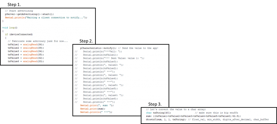
The tutorial includes as well a ESP BLE-Sketch to read serial values the ESP sends via Bluetooth. I used this sketch and did some further coding (with some help :D)
Hardware
My lessons learned of the hardware part of my project is that you should connect all the wires via bread board or in my case to bread boards because the microcontroller is quite broad. I saves you a lot time in case there are some mistakes and soldering tin. The pictures above are some impressions of my different attempts.
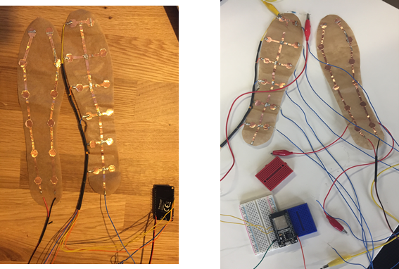
In my first try I had multiple short cuts because I missed to include the resistors. We spend a lot time of think about where to place the resistors. Finally I came up with this solution:
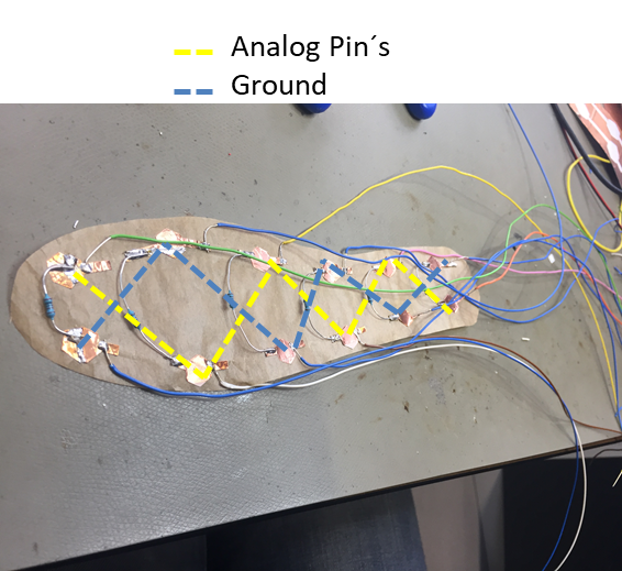
Every analog input has to be connected separetly with ground and a resistor. My supervisor in the Lab told me that the ESP indeed has 14 analog input pins but when I am using the Bluetooth function I only can use 6 of them ( ADC1-Pins GPIO 36 - 33). That was not really what I planned but now I could use the free pads to place ground and connect every single pad with a single ground pad and connect this two pads with a resistor of 1K Ohm. I did in a zigzag format because from my point of view it covers load with 6 contact points best. For this I had to change my soles. I used the side planned for VCC for ground and the analog pins and the other way around. The advantage was that I added some copper foil to connect all the pads before therefore I only needed one wire for the VCC part.
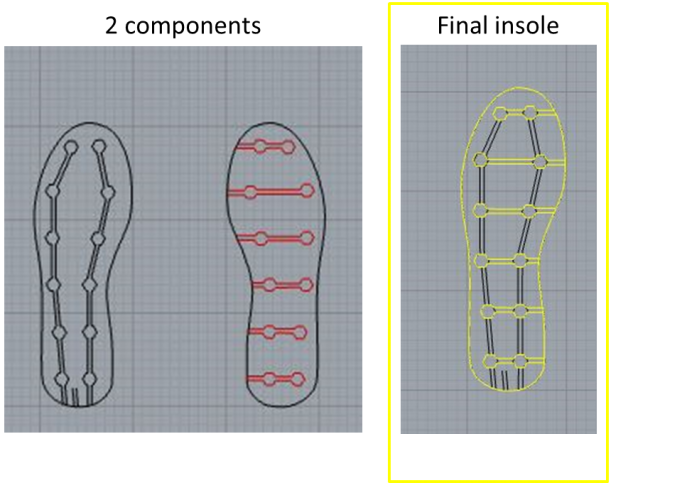
The semi conductive foam I am using is Polyethylene PE553 and has a hight of 5mm. To increase stability of the whole sole, the protection of the resistors and the comfort of the user I attached non-conductive foam with the same hight and the same strength. I cut it as well in the laser cutter and I could simply use my Rhino sketch by replacing the conductive pads with the semi-conductive pads. See the final components:
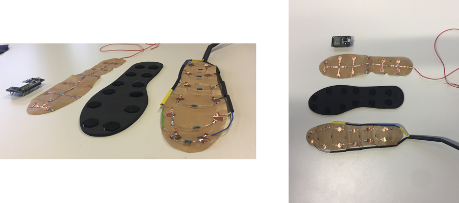
Finally, I pasted all three main components with double sided tape together and heated up the cable hoses with a heat gun.
Building my first Android app with Thunkable
In the tutorial it is recommended to work with Thunkable, it is a visual app-building tool where anyone can build their own mobile apps (iOS or/and Android) without coding. That was really good for me because the app of a friend of mine worked but I could not really change things be myself and furthermore the design part is very easy to make with Thunkable. It is also said that their iOS support is in an early stage and does not have Bluetooth functions yet, therefor it is recommended to build an Android App, so did I.
In the instructions include as well a demo sketch for the App which I used as a basis to work with. It takes some time to get used to it but there are a lot of good and comprehensible tutorials.
That is how the demo looks like:
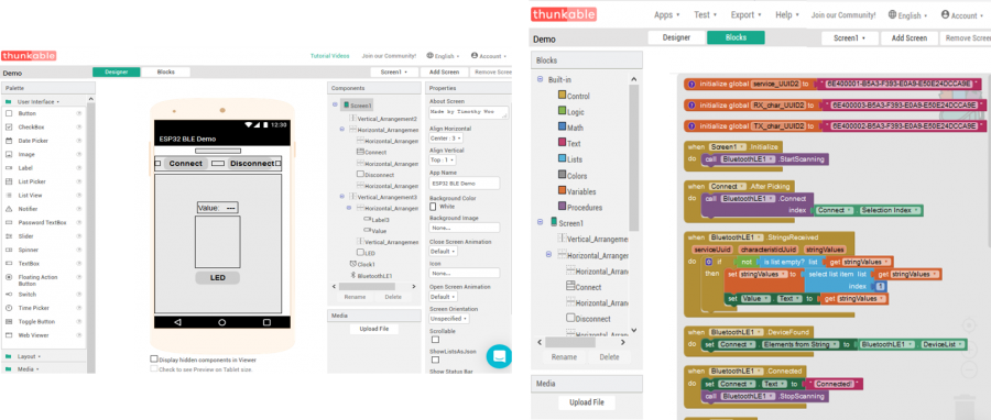
Little Programming:
Nevertheless, Thunkable gave several opportunities to avoid coding but I had to modify the data which where send to the app. Because the variables a still provided by the ESP and this has to be done in Arduino IDE.
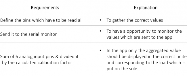
My requirements have been:
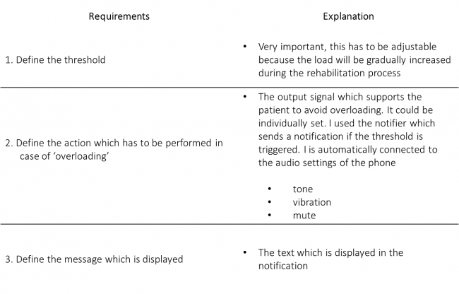
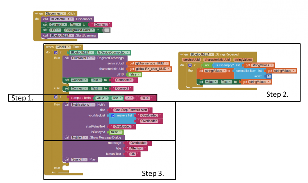
Final appearance:
Supportive devices:
Support Board:
To connect the board more easily to the wires I used a blank board. I had the challenge to connect 6 ground wired to one pin. Due to the blank board I could connect it easily without touching other pins. Furthermore, I could hid the cables in the newly created space.
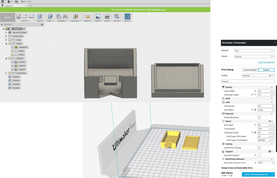
ESP32 Box
To protect the board and to make it wearable for the patient I printed a box for the board. I downloaded a sketch and edited in Fusion 360. My last work in Fusion was some time ago therefore I needed several attempts until the box fit for the board including the support board.
Energy source:
The VCC pin is running with 3,3 Voltage and we planed to work with a Lipo batery whith a 3,7 Voltage. According to the datasheet (page 2) the operating Voltage/Power supply is at 2.3 ~3.6V. Therefore, I had to install a Voltage divider to decrease the output Voltage which goes to VCC to < 3,6V. I soldered the wires but afterwards we recognized that the handling of this battery will be difficult because we did not include a switch. Furthermore, I was not really happy that I had to print my ESP box again. Hence, my supervisor gave me the hint that I could use a powerbank as well which could be directly connected to the micro USB port. I is not that compact but it has the advantage that I can switch on and off the sensor easily.
Final Presentation
On the 27th of March I had the opportunity to present my final project. We had a tough time schedule and I had some technical issues but you can find thepresentation as well as a clip online.