Table of Contents
Assignment: E-Textiles & Wearables
This week we had an introduction class by Hannah Pierre Wilson and Mika Satomi about E-Textiles and Wearables. Our first exercise was to create a simple circuit withe an opening blink LED.
We repeated some basics which I vaguely remembered from physics class. First we measured the resistance of different fabrics because the degree of resistance has an impact of the energy flow. My teacher in physics always said: “Energy seeks the path of least resistance”.
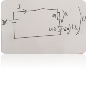
I used a battery with 3 Volt but the LED we want to blink, needs only 2,2 Volt therefore we need a pre-resistor. With a current of 0,02 A to operate the LED I needed a pre-resistor with 40 Ohm:

 See calculation:
Ohmic Law: R = U/I
(3 Volt - 2.2 Vol) /0,02A = 40 0hm
I used conductive threat as the pre-resistor. 10 cm of conductive has a resistance of 20 Ohm therefore I worked withe 20 cm of conductive thread. As switch I used conductive material which was connected with the conductive. By pressing both parts of conductive material together the series circuit was closed and the LED blinked.
.
26.10.2017 l FabLab Session
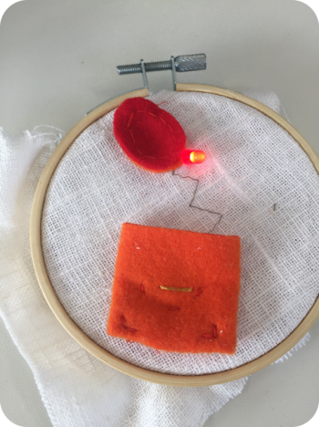
After we created the simple circuit we should sew a circuit. I used the same materials like in the simple version. 
Additionally I needed a pocket for the battery. With the multimeter I conducted some connective checks to monitor the connectivity and the correct processing.
I tried to work only with the 40 cm conductive threat because if the resistance is higher than needed the LED will blink less brighter.
Result:

Material I used:
- Felt: non conductive, is used as an isolator
- Conductive Thread: (to connect single parts), consists mostly out of metallic vaporized silver threads. Depending on the metal used and the layer thickness the resistance varies. Commonly the resistance is 0,5 Ohm per centimeter. For long distances it could be helpful to sew the thread multiple times, to decrease resitance by increasing the surface.
- Conductive Fabric: Follows the same principle like the conductive thread. It is washable and fusible to other textiles. I experimented a lot with these fabric in my final project. I have to look up the detailed data sheet for the material we used and I will updated then.
26.10.2017 l FabLab Session Arduino
The second half of our FabLab session we got an introduction into the field of ARDUINO. It is a physical-computing-platform which consists of soft- and hardware. The hardware is a E/A-Board with a microcontroller which has analog and digital in - and outputs. The software is available as open source where you can code the microcontroller.
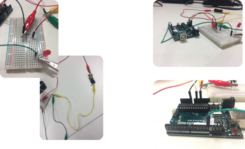
Our first code was to blink an LED. Therefor I put a LED in the so called bread in whole 1 and 2 these two wholes are not connected. (Each row of numbers are horizontally connected).
I connected the LED with the ARDUINO therefore I grounded the negative part of the LED and the positive part was connected to 13 (digital) which has the correct resistor.
 Void setup = settings,
Void loop = what am I going to run
After the successful blinking of the LED lamp we did an advanced circuit with a “sensor” where we measured the different currents while pressing it. (I made some videos and have to find out whether it is possible to upload them here.)

