Week 9
Last Week | Final Deliverable
In the end I didn't manage to test the CNC-3D printer, the genuine Arduino came too late to be able to relay on being able to finish that way. So instead I tried to focus my full energy in making a final 'proof of concept piece'.
The dress consists of 160 modular pieces. Each piece takes about 30 minutes to print, which means that for the total dress 80 printing hours are needed. Which is about 10 full days of printing. This is exactly the reason I think a bigger printer area is needed: now about half of the material printed goes to connectors that are not highly necessary. A normal t-shirt for example would have about 4 connection lines. Along those pattern-lines I can imagine a modular connecting system being in place. However if I would make a t-shirt with the small printers available now, I would need about 84 modules * 3 connecting lines per module = 252 connecting lines. All these lines need connectors and thus added (unnecessary) material.
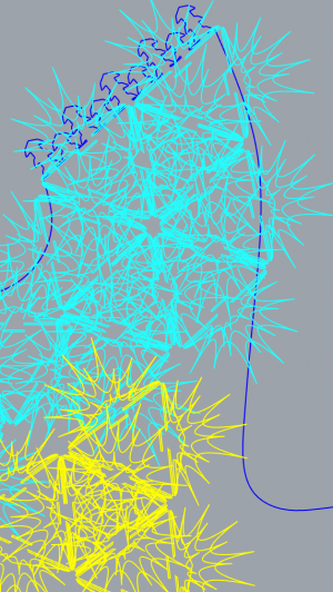
Below you can see how messy the design got at one point. I needed to select the pieces one by one, giving them a different colour to know which I had counted and which not yet.
Shown below is half of the front and the back of the dress shown:
(Without this metal support I would have no clue anymore which piece belongs where). And then all that is left is 3D printing like crazy to be able to show this dress on Thursday 29th of March at the final presentation.
The illustration that I used for 84 pieces out of 160 is this.
Week 8
Material Xperience 2018
Next to creating a lot of small tests with the new finding I spent this week preparing and exhibiting PerFlex.design at the Material Xperience.
Week 7
Building | The Filament Holder
During last week I must have been very tired, because there were quite some mistakes in the design. During the day I managed to fix all of them and finish the filament holder design. Unfortunately this is the only picture I saved on my computer; (later on I'll try to make more pictures)
This is attached to the side of the filament holder to hold the board and LCD screen. I lasercutted it out of 6mm thick plexiglass. The text was meant to be engraved, but only after I cut the piece I found out that instead of solid back engravings need to be outlined as well. Because of this small mistake my final version does not have the text.
Learned | Flexible Filament Ultimaker
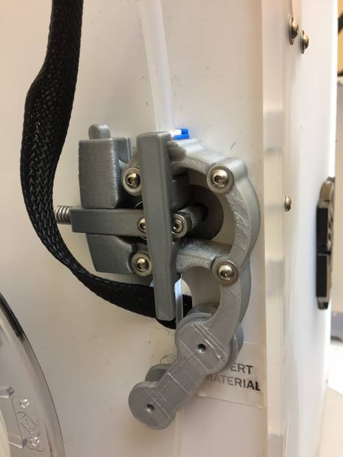
During my stay at CODA I learned that the Ultimaker doesn't automatically have this feeder:
For me that came as a big surprise, but now I also know what is the difference. The feeder that I've been used to, is specifically for soft filament and doesn't do too well with rigid filaments.
I found this site that has a similar alternative feeder if you want to start working with soft filaments.
Discovery | 3D printing with multiple colours
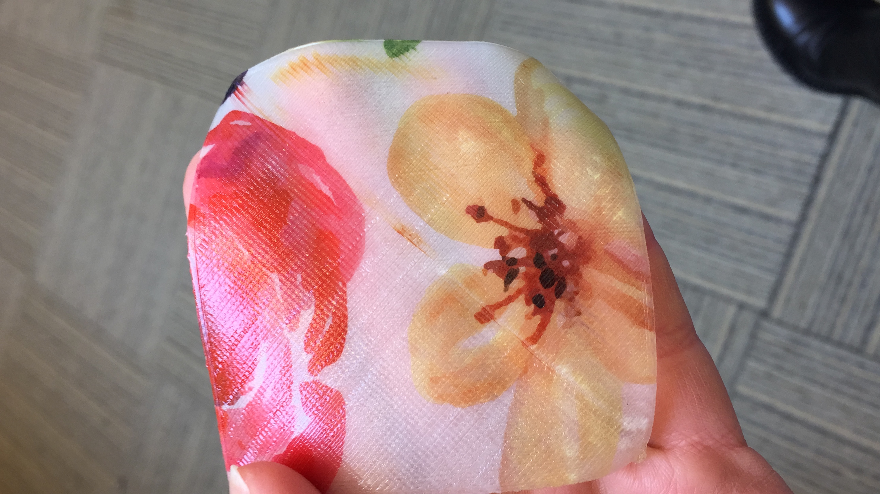
At the end of the week I discovered a new way to add colour to 3D prints together with Troy Nachtigall.
Visit Japan | Fablab Hamamatsu
Fablab Takespace has a big CNC-mill too, yet not the Shopbot. Looking at machine with the attachment I designed in mind, it turns out that the design might not be as universal as I thought. Also I thought most labs would have a shopbot, this assumption might not be reality. Therefore making the design less versatile.
Week 6
Building | The Electronics | 24V
FAILURE Great Lesson
Today I looked up which part should be connected where and how. On the site of Recreus there are multiple videos on putting together their Extruder. Since that is the piece consisting of most small parts I decided to start there. For the time being, I'll be using the broken build-plate below, for the testing this should be more then big enough.
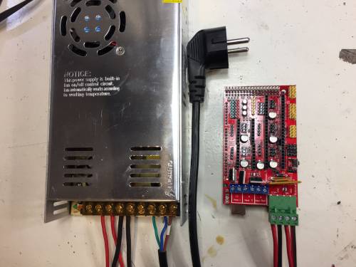
Going through the electronics with Emma, there is one most important lesson to learn: “Tested up to 24V.” doens't mean that the board should get 24V. Meaning; the adaptor I bought is much to heavy for the board. Luckily I waited with connecting everything to the power supply until Emma would have said it was okay, if I had not, I would have fried the board and maybe even more components.
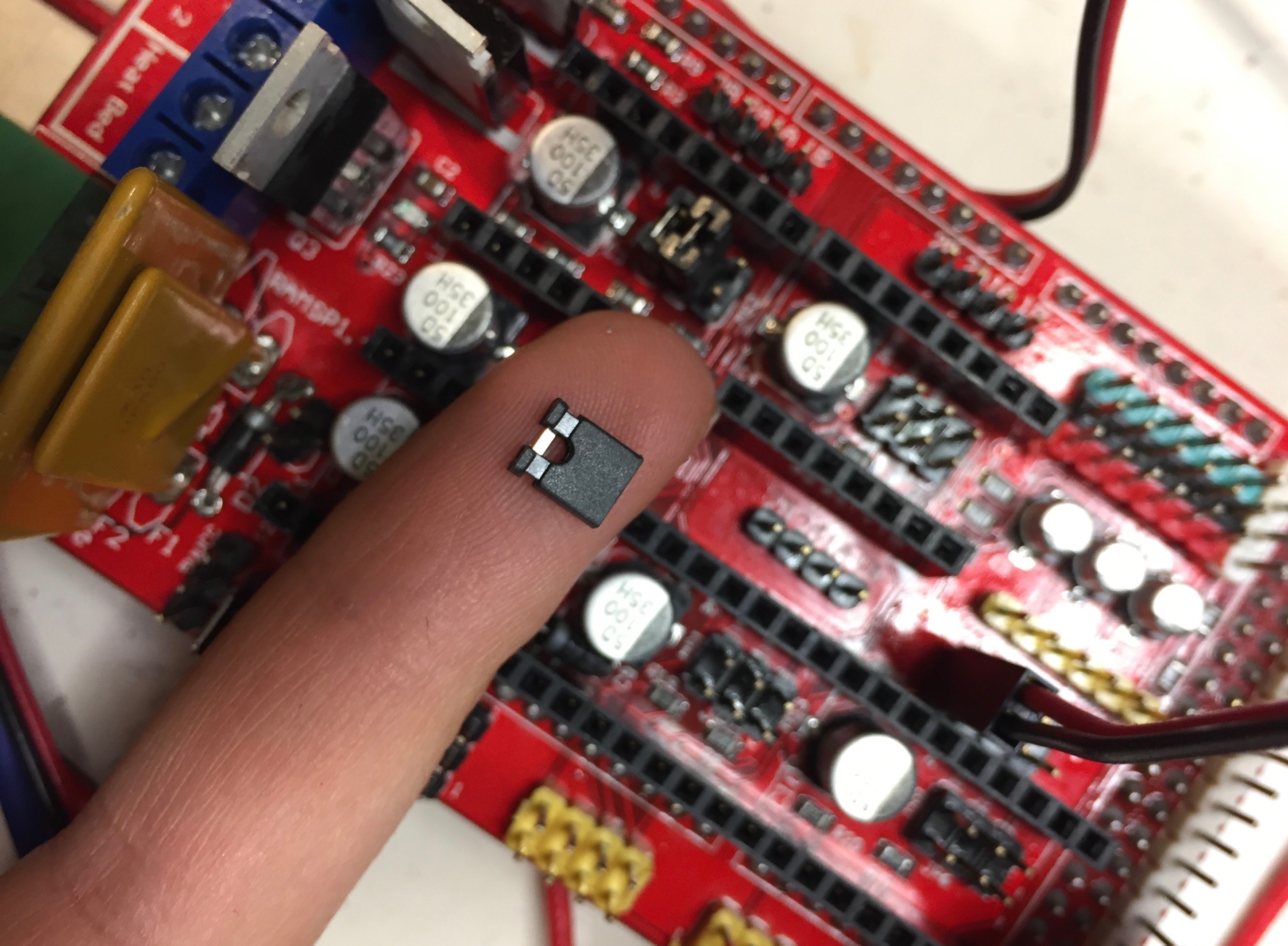
The jumpers control the precision of the motor movement. To have the most precise stepping (1/16 micro stepping), I inserted 3 jumpers underneath the extruder stepper-driver.
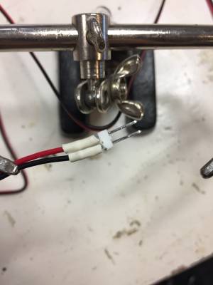
The thermistor's cables are too short to reach the board at the top. So, for them I needed to lengthen the cables with one of the sets I bought. The wires however did not have a connection part yet, so in the pictures above you can see how I soldered them.
Building | The Electronics | Marlin Firmware | Why NOT to buy a clone
FAILURE Great Lesson
This site give a step by step guidance on how to install the software on the RAMPS 1.4 board.
So the first step is downloading Arduino and installing the Arduino 2560 USB Device Driver on the software. Next you download the Marlin 3D Printer Firmware. For the display you download yet another library.
Step 1 of the guidance steps I found out why it might have been smarter to buy a genuine Arduino Mega 2560, instead of the clone. The Arduino software doesn't recognise the serial port as being in use. Which means I can not upload any code to my Arduino clone. I tried to download another library, however this doesn't seem to work yet. Unfortunately…
Proterface could help with walking though the electronics, once the computer recognises it.
Epiphany | The Electronics | LCDscreen placement
In the setup as it is, the LCD screen and SD card input are on top of the moving part of the Shopbot. Which means you need to climb on top of the machine to be able to change the machine settings. This is of course not too smart. So lengthening the data cables would solve this problem. Then the LCD screen can be at the side of the machine, which is always easily accessible no matter the position of the printer head.
Building | The Electronics | Steppermotor connection
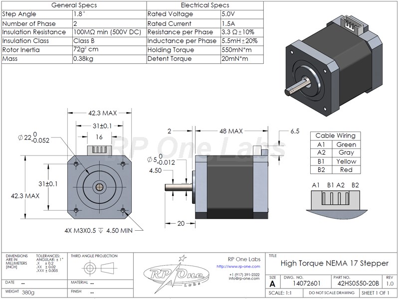
The cable socket bought does not actually fit into the Nema17. So, these need to be loosed and replaced into a new pinconnector.
Building | The Extruder Holder
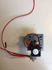
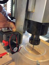
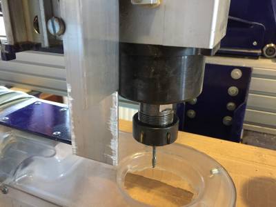
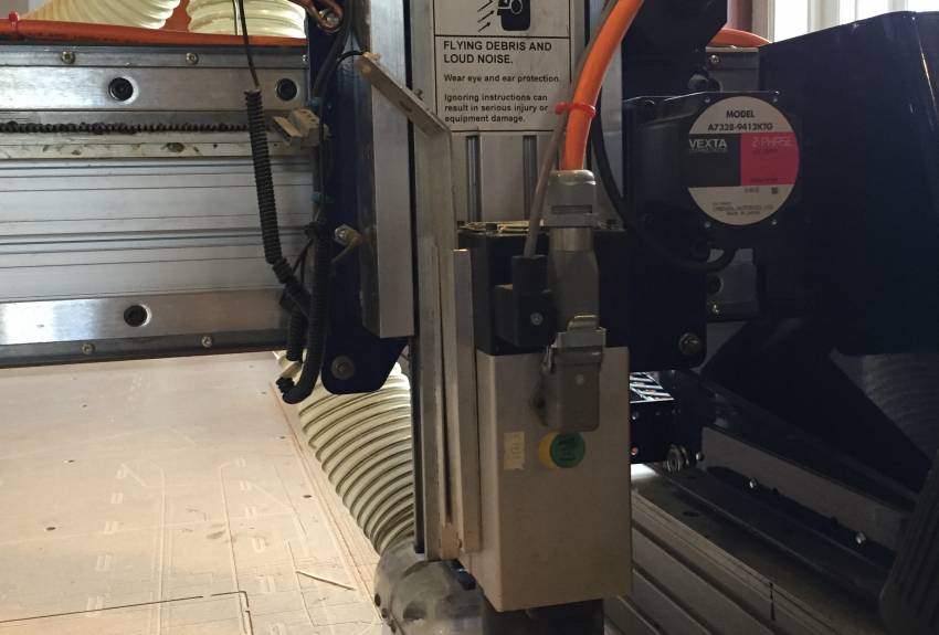
I work with 2.85mm filament, so that is the button and nozzle I put on the extruder. Also I took a better look at the U-profiles on the machine and found out that these are attached to the machine with double-sided tape. Which is okay, when it only needs to carry the Z-axis tool, for the extruder (heavier) it needs to be quite stable and secure. So, I needed a different method of attachment then the u-profiles.
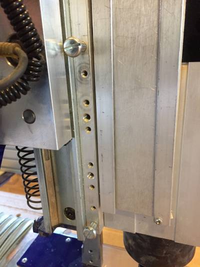
Luckily Ruud helps me thinking in the morning and we notice the screw holes in the back, yet still attached to the moving part of the Z-axis. This part has 'english screws' instead of using the metric (kind of) system of M3,4,5 ect. they use inches for the turning part of the screw distance as well. So a normal (M5) screw might seem to fit, yet after a few turns you can feel that it is not possible to turn it any further.
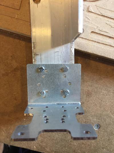
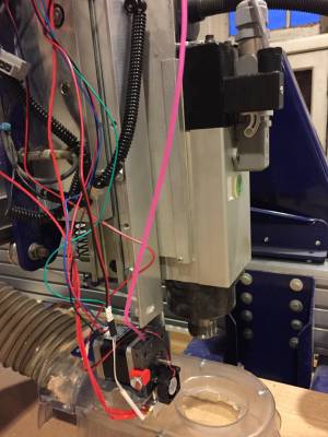
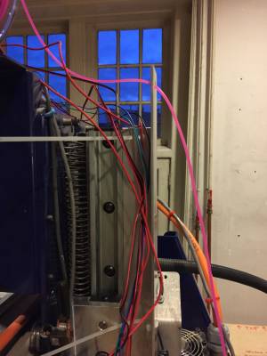
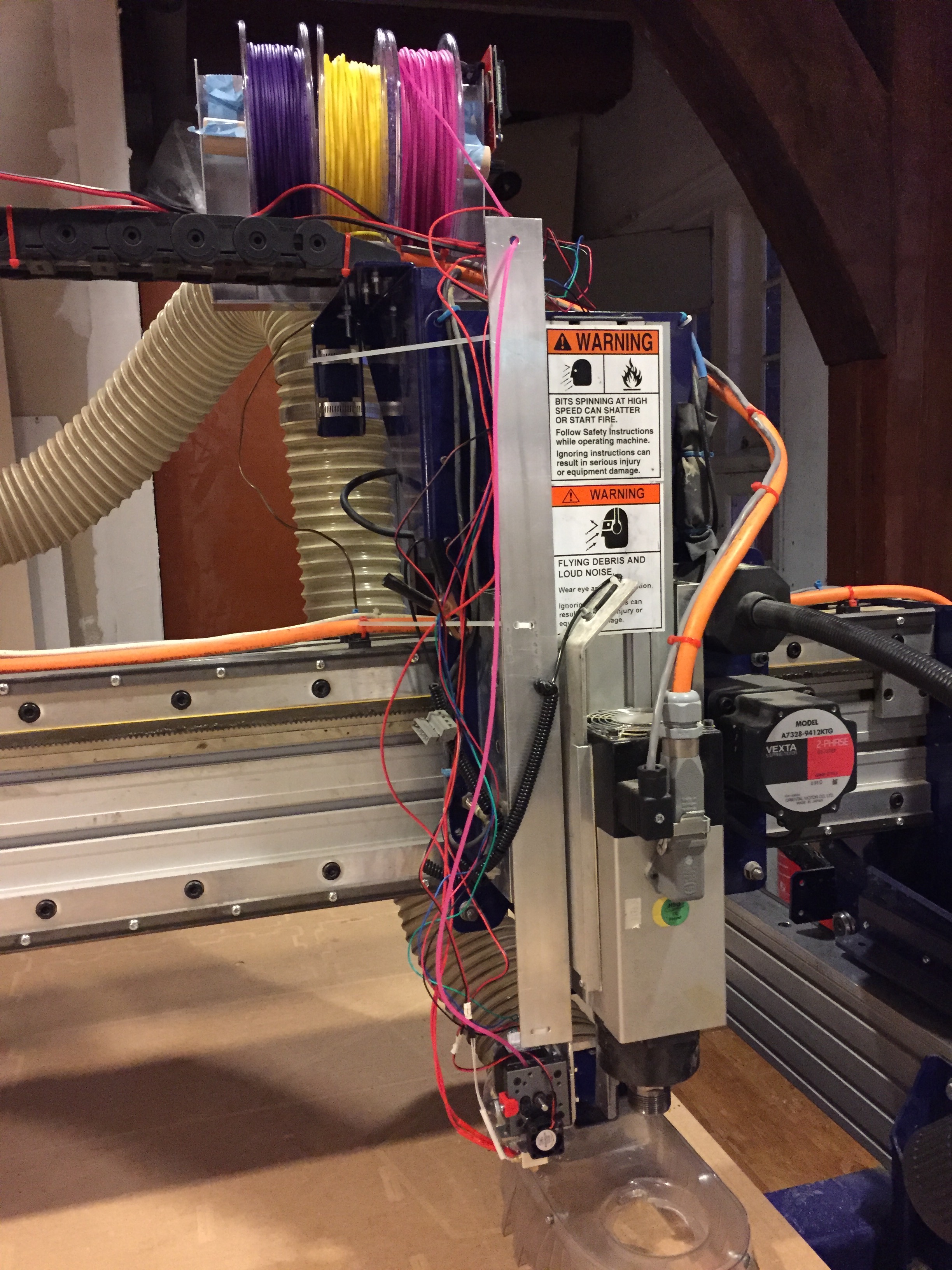
With left-over material from the lab I designed a setup piece with which the extruder can be attached to the machine.
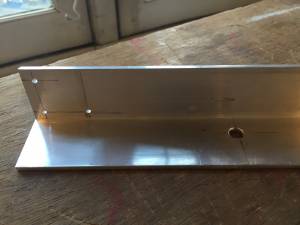
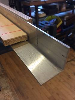
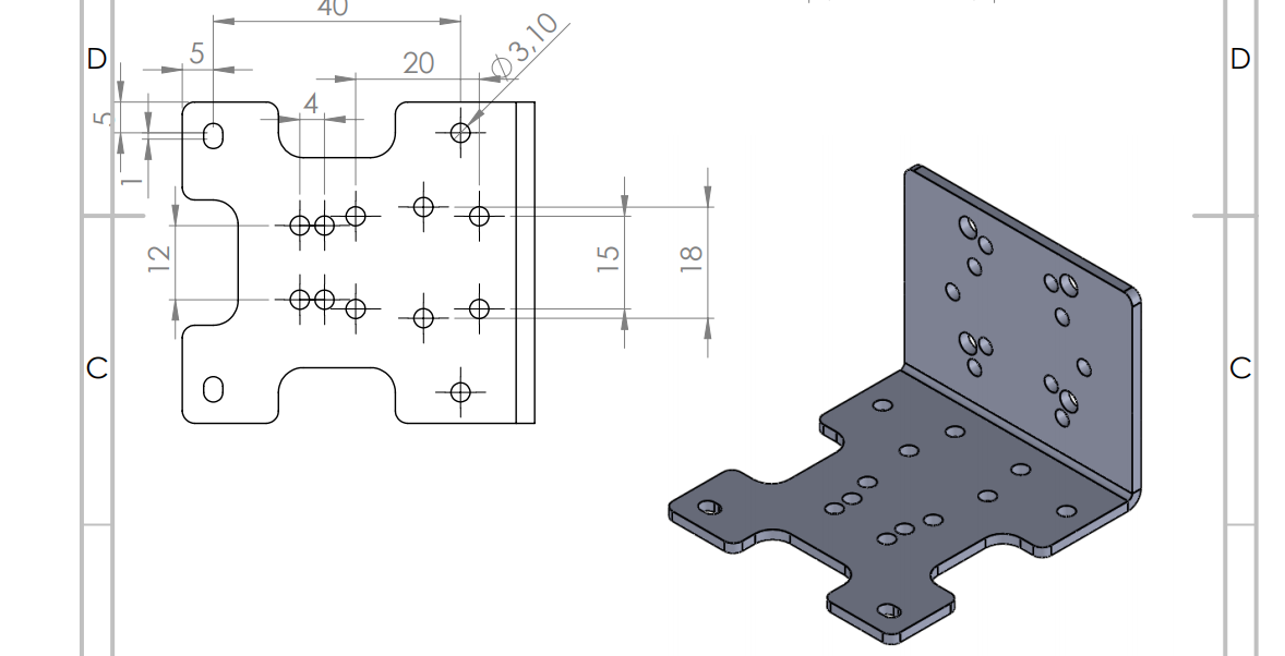
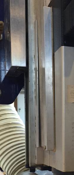
What I found was a 40x40X3mm aluminium hook. On opposite ends I took off 6cm of one side of the hook. The best way to get what I mean here is to scroll a bit down to the overview pictures of the object.
The bottom side has four holes 23mm apart from each other to hold the universal support with M3 screws.
Over the length of the material there is another 6holes made to put tiewraps through to neatly hold the electronic wires later on. The 8mm big hole at the top is mean to lead the filament through. The placement of these holes are not necessary to place very precisely.
And finally four holes to connect the material to the machine. These holes need to be made with utmost precision! pic. notebook on measurements
Midterm Feedback
During the midterm Neil Gershenfeld told me to look at DIY knitting and weaving techniques. His tip was to use actual thread instead of using filament; to 3D weave or knit instead of extruding. He told us that he is not a fan of 3D printing, explaining that this is only a little part of the bigger picture: digital fabrication. He advises us that if there is another way to do your project, stray away from 3D printing.
A different general advice he gives us is to research more on the background of other projects doing done in the same direction. Reading up on what they are doing and how they did it, will give us more depth. And, most importantly makes us able to answer the question: What does my project in comparison with the other ones out there? What does my project add?
The last feedback he gave us, was on how diverse the different projects are. And thus, what are the boundaries and the requirements of a Fabricademy project? Asking us to pick realistic boundaries, goals that can be achieved within the three months (having future follow up plans is okay though). He asked us: How and when do we evaluate our project as successful?
As for the first note he made. Choosing something else then filament, is not possible for me anymore. Since I already bought all the building material and since time-wise it is not possible to make such a big shift in concept anymore.
As for the second feedback; what does my project add? If I succeed there will be an easy-to-follow instruction plan on how to turn the Shopbot into a 3D-printer, which would make the machine even more multifunctional. Fablabs that otherwise would need to buy a big 3D-printer for certain projects can now build it themselves for less then €800. As an addition to that I will be the first one who will document the process CNC-mill to 3D-printer properly. So far I know of tree to four people that have done this on the internet of whom only one was fully described (but also quite different from what I'm doing).
My goal at the moment is building the 3D printer and making it work. Although I would like to do so much more, I think this is a realistic goal for three months work. It might even be a bit of an overestimation, but I know that although it might be simple when looking back, there are a lot of unexpected troubles that need to be solved when trying something for the first time.
I would see the project as successful if I would be able to print a small (30x30x5mm) cube though Cura. From there on the future plan of making the connection to Grasshopper and building a fully parametric closet is one step closer.
Building | Final result of the week
Week 5
Building | Rhino Support
As shown below, none of the holes in the support are useful to connect the already existing structure and the support together. So, another piece, or method, must be used to accomplish this.
And. You might wonder why I bothered to make this in Rhino, whilst I knew the furthest difference between the holes was 30mm from the datasheet and the distance between the u-profiles was approximately 50mm - 20mm = 30mm. So I validated the obvious?
Making 3D-models in Rhino is something completely new to me. Although I have an Industrial Design bachelor, I never followed any courses on making 3D models. That's why I really enjoy getting to know Rhino and I believe the best way to start is by rebuilding a technical description. (as the one given in week10 for soft-robotics and the datasheet mentioned before)
Building | The Extruder Attachment to the Shopbot
The extruder of Recreus comes with a really handy universal support, so I'm taking this as a starting point my support to the Shopbot head.
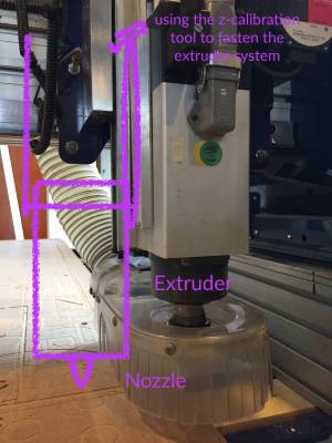
Also, the Shopbot at Fablab De Waag comes with a tool holder for the z-axis calibration. I'm not too sure is this is a standard thing, but I'd like to use this as the attachment point.
After taking a closer look at the attachment it seems that this is hand-made, cleverly simple, to give the tool a spot. The screw at the bottom makes sure that the tool doesn't fall through the u profiles.
Now there are two options: either attach the universal support or make a support that slides inside the u-profiles. I think it saves material and costs to attach the support to the outside of the u-profiles. In order to do so though there will be screws through the profile, which will shorted the amount of space for the z-axis calibration tool.
Learned | Cables, cables, cables??
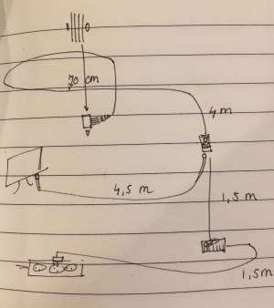
With the help of this site it's possible to calculate what diameter and AWG you need for the cables. As it turns out, the cables are much more expensive that I had expected. So there are two options: a) to put the board next to the filament-holder, which would save 70m of cable from the extruder to the board, yet add 6,5m to the cable from the board to the power supply. Also the USB A-B type cable from the board to the computer would become 8m instead of 4,5m. Emma told me that data transfer would not be possible at this length. In the worst case scenario it's possible to solve that with a LCD screen and SD card input (€25,50).
So, RAMPS board next to the filament holder:
- Extruder to board | 24 AWG | 1m | €4,00
- Extruder to board | 22 AWG | 1m | €2,00 (Steppermotor)
- Board to Power supply | 12 AWG 4mm² (41A max) | 8m | €172,00 ???!
This shows that the power cable is quite expensive! So although it might save a lot of cables in the beginning, the one cable that will become longer is an expensive one.
So, RAMPS board next to the machine (after the 8m band loops):
- Extruder to board | Steppermotor 2,0A | 15 AWG 1.5mm² (11A max)
- Extruder to board | Fan 0,06A | 26 AWG 0.5mm² (5A max)
- Extruder to board | Hot end 1,7A | 16 AWG 1.5mm² (11A max)
- Extruder to board | Thermistor 0,024A | 26 AWG 0.5mm² (5A max)
- Board to Power supply | 15 AWG 1.5mm² (11A max)
This is probably the cheaper option. However, I find it really difficult to find a site that sells the exact cables described above. So what Emma advised me to do, and what I did in the end, is buying the 1m cables for now. See how much current is actually used and based on that make a final decision.
Materials | What to buy | Final List:
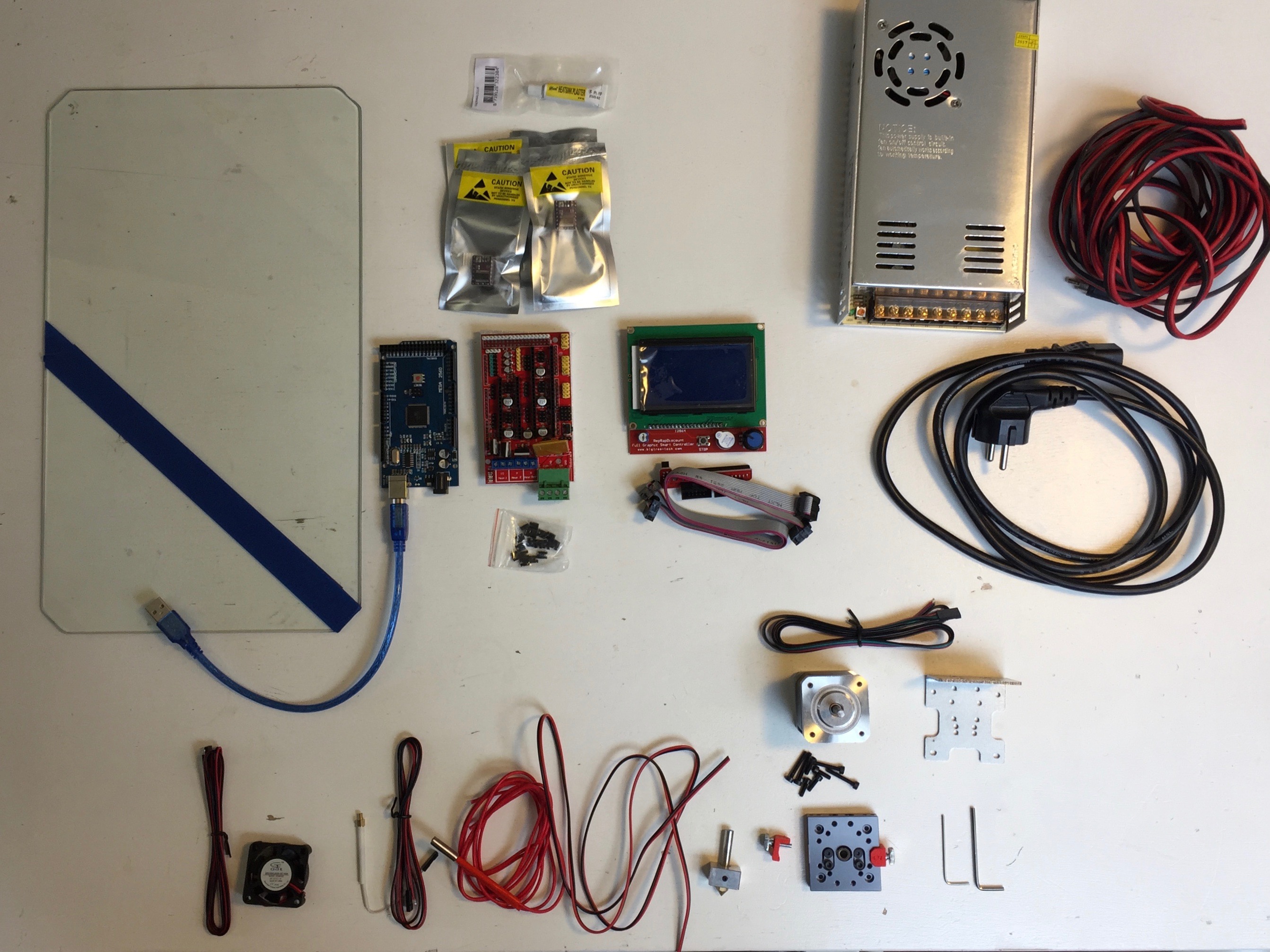
- Electronics | Steppermotordriver (4x) and Thermic Glue | €25,00
- Electronics | RAMPS board 1.4 | €14,50
- Electronics | Arduino Mega 2560 (clone) | €16,95
- Electronics | Power Supply (24V, 15Amax) | €42,00
- Electronics | RAMPS 1.4 Smart Controller LCD | €19,95
- Electronics | Extuder Recreus (24V) | €192,39
- Electronics | Steppermotor for the extruder | €14,50
- Cables | Hot-end | 22 AWG 2-vein cable | €1,25
- Cables | Stepper | 4-vein cable | €2,00
- Cables | Thermistor & Fan | 2-vein cable | €3,00
- Cables | Power Supply | 1.0mm² Flexible core cable | €4,95
I wanted to make a Fritzing scheme of the extruder ect. however, Fritzing doesn't offer most of the parts standard.
On this site someone managed to make a scheme of a 3D printer. (below)

Week 4
Materials | What to buy | Electronics:
- steppermotordriver | €5,75
- OR: Steppermotordriver (4x) and Thermic Glue | €25,00
- RAMPS board 1.4 | €14,50
- Arduino Mega 2560 (clone) | €24,50
- OR: Arduino Mega 2560 Rev3 | €47,50
- Power Supply (24V, 15Amax) | €42,00
- Extuder Recreus (24V) | €192,39
Which gives a total of €321,39 at its most expensive.
Materials | What to buy | Cables:
Later today, after discussing my plan with Cecilia I discovered that I missed a loop through the belt on the long side of the machine. Which means there will be another 4m added to all cables that go from the extruder to the board.
- Extruder to Board | hot end | 2-vein cable 8m | €12,00
- Extruder to Board | thermister | 2-vein cable 8m | €12,00
- Extruder to Board | fan | black/red 2-vein cable 8m | €12,00
- Extruder to Board | steppermotor | 4-vein cable 8m | €16,00
- OR: Extruder to Board | steppermotor | 4-vein cable 8m | €6,00
- Board to Computer | USB cable (type B-A) 5m | €4,95
- Board to Power-supply | 2-vein cable 1,5m | €0,98 | NOTE: this cable can only handle up to 2,5A, which is probably not good when the power supply can give up to 15A.
- Power-supply to Power-socket | (European) Cable 1,8m | €5,00
- OR: (European) Cable 2,0m | €3,71
Which gives a total of €62,93 with the most expensive options. I think for the cables it must be possible to save a lot of money by making the cables myself when buying a huge roll. Especially notice the (HUGE) difference between the pricing in the two sites. Also Ruud has given me the tip that when 8m of cable is used a thicker cable might be necessary due to the added resistance.
Materials | What to buy | Filament:
- Filament Filaflex 82A 2,85mm 500g | €33,76
- Filament Filaflex 70A 2,85mm 500g | €45,86
I have really good experiences printing with Filaflex, but of course there are different other options that print flexible as well.
Materials | What to buy | Tools:
- Ceramic Screwdriver | €3,50
- Core plier/cutter, Wire stripper | €22,50
I have no more budget for the filament and tools section, so I'll need to think of a different way on how to get those.
Materials | What to make/buy in the future
- Glass buildplate, 1220x2440mm, 6mm thick | €169,29
- OR: Glass buildplate, 1220x1500mm, 6mm thick | €104,07
- Felt Glass plate sleeve mainly protection purposes when the glass plate is not in use | €39,80
- Filamentholder | €25,00
- Extruderholder | €25,00
Learned | Glass buildplate
Reading this forum I figured out more about the glass that is used for the 3D printer bed.
Usually borosilicate glass(borosilicaatglas in Dutch) is used. Advantages of this glass type is that it is heat resistance up to 670 °C. The disadvantage is that it is more expensive. Because I'll be printing with Filaflex, which doesn't need a heated bed, I'll be going for a cheaper option: tempered glass (gehard glas in Dutch).
In the forum someone mentioned 4mm thick glass, I think because the printing bed will become rather large that I'll go for 6mm thick glass.
Week 3
For this week I need to figure out how the Shopbot works and how it is connected to be able to plug in the data I want to plug in. So the goal is to be able to move the X,Y and Z-axis separately via a different board.
Learned | How to build a 3D printer?
https://www.youtube.com/watch?v=46eq9fxaEds&list=PLBuiTTpnAMwcDGwIIBbVGtsCXVkUxjhEn
Learned | What have other people done so far?
A simplified to do list with the most difficult task at the top:
Connect the X, Y, and Z-axis to 3D printer drivers or connect the current drivers to elsewhereAttach the drivers&board to the usual 3D-printing screen (probably Prusa)- controlling the extrusion stepper and heating via the shopbot software
- Heating system for the nozzle
- Make an attachment system for the nozzle
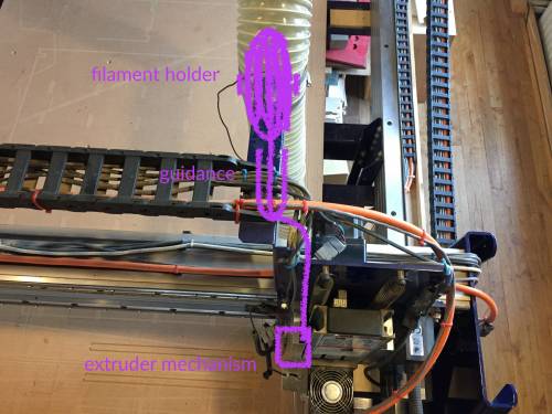
- Make a filament holder on to of the Z-axis (piece that moves along with the shopbot)
http://www.shopbottools.com/mProducts/prSalpha.htm, this is the machine we have in De Waag Society.
https://github.com/fellesverkstedet/SLA-3D-printing-with-ShopBot-CNC-mill/tree/master/Source%20files, someone who managed to make a SLA printer from the shopbot. Maybe I can use the software he wrote (Rhino&Grasshopper input).
https://www.youtube.com/watch?v=z0esDFBP4gY, someone who already managed to make the connection piece for the nozzle/fan&heating element.
http://www.instructables.com/id/Combination-CNC-Machine-and-3D-Printer/, someone who explains step by step how to build a 3D printer ànd CNC-milling machine.
http://www.shopbottools.com/ShopBotDocs/files/SBG%2000142%20User%20Guide%2020150317.pdf, I guess this will be my best starting point.
http://www.shopbottools.com/ShopBotDocs/files/SBG%2000202%20ATC%20Retrofit%20Board%200.7%20&%200.8%20Install%20Manual%20-%20Electrical%202014%2011%2014.pdf, this is a guide on how to put together the electronics of the shopbot and thus studying this I might find out where to intervene.
http://www.talkshopbot.com/forum/showthread.php?15282-CNC-and-3D-printer, apparently there is a different fablab that has made this addition. In contacting Fablab Tulsa though they didn't know what I was talking about. So, it is a bit unclear who made this design.
Materials | What do I need?
- power-supply board
- 3D printing board
- nozzle
- glassplate (buildplate)
- power-supply (12 or 24V)
- socket
Week 2
This week we went to Bioracer with my sponsor and Marina toeters. During the visit we got shown around the whole company. It's absolutely great to see that one company can do so many factors of the system. https://vimeo.com/250427540, the link to the video.
Week 1
Filling in the questionnaire with one of my first users something dawned on me. The question: “If you would be able to buy your favourite garment in new colours and materials, how likely would you be able yo love it equally?” with a scale from 1 to 7, only says how likely the user would love it equally. So when the user says they won't love it equally I do not know whether there is a positive change “I would like it much more” or a negative change “I would not like it anymore”. This is something to be taken into account.
For the first day I made a planning for the upcoming months and a survey to find out what my user group thinks about the topic. Which is much more precise of course than what I assume they might think.

