Table of Contents
Week 9: E-textiles & wearables II
For this week's assignment, I created a chest belt that senses a deep breath with the fabric stretch sensor over the diaphragm which then triggers the vibration motor at the back of the belt. The idea is that for people who are breathing heavily, ie who may be stressed, will be reminded to calm down due to the triggering of the vibration. To download the file for the electrical traces, visit: https://oscircularfashion.herokuapp.com/project/-L6SQ-_oojvyopvBFs9F
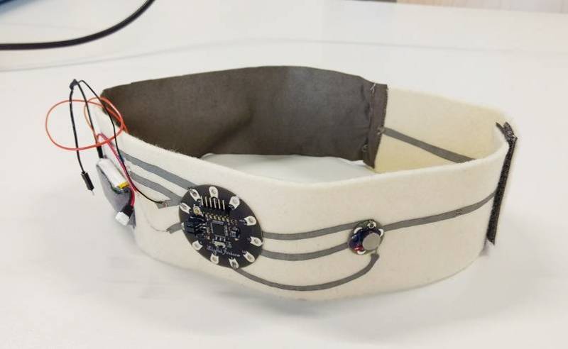
The Process
First of all, I needed to simulate the sensing and actuation with the components, therefore I cut out a piece of stretchy conductive fabric (Shieldex Tex) that covered the diaphragm (based on my own body). In order to set up the prototype of the fabric and vibration motor, I had to figure out what resistor to use for the connection. I measured the resistance present in the fabric when at rest (not stretched), multiplied this by 5V and divided by 2. This showed that I needed to use a 100 ohm resistor.
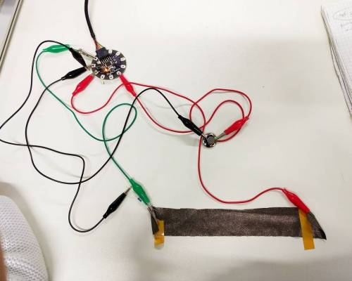
I then set up the test with the fabric sensor, a Lilypad arduino and Lilypad vibration motor. I connected one side of the fabric sensor to the VCC of the arduino and the other side to the analog pin on the arduino and also the resistor and ground. For the vibration motor, I connected ground to ground and the trigger side to pin 9 on the arduino.
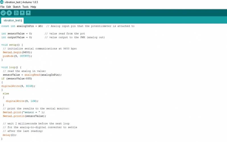
I found some code on the web that suited my needs, in that it included a threshold (sensorValue) and an actuation when the threshold was reached. I changed the pin numbers and threshold figure, and added a serial print of the sensor value so that I can see the results on the serial monitor. After some time testing and playing around with the threshold figure, I managed to trigger the vibration motor successfully when the threshold was reached.
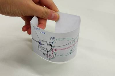
Knowing that these connections worked, I then designed how to make the same connections into a chest belt. I drew this out on some paper so that I could visualise the connections, especially when it would be around the body and closed. I realised that I needed to make sure the belt could be put on and taken off, but also that the circuit was closed when on. Therefore I decided I needed to use conductive velcro to fasten the belt on and close the connection when on the body.
Satisfied with my rough sketch, I designed the traces in Rhino to be cut out in non stretchy conductive material. To do this, I imported the images of the Lilypad arduino and vibration motor (to scale) so that I could use them as a guide for making the traces in the correct position.
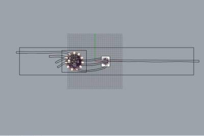
I then needed to produce my belt. Using my own body as a guide, I cut out 2 pieces of felt and used the sewing machine to sew the conductive velcro to each end.
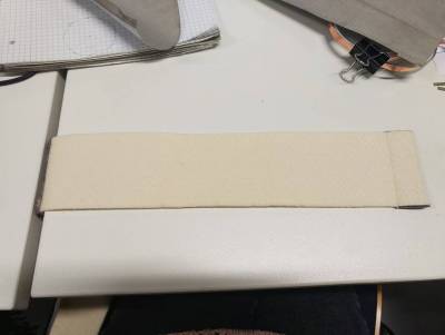
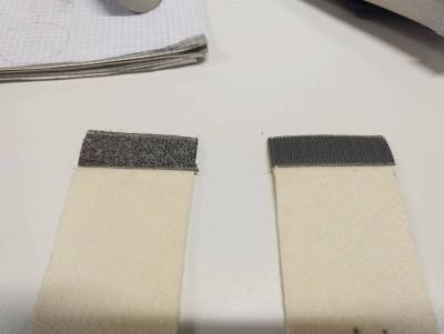
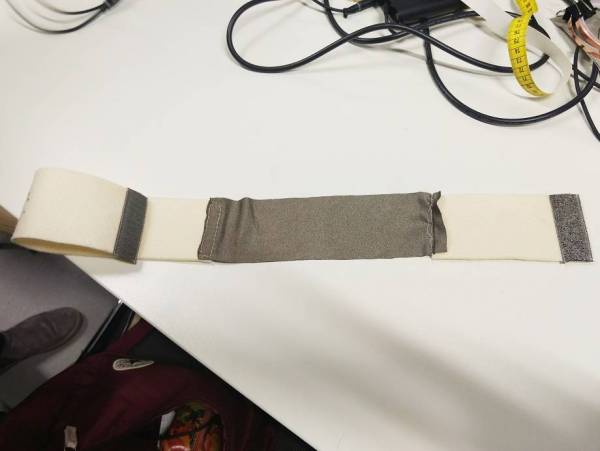
I then sewed the felt parts to either side of the stretch sensor, as below.
I laser cut my traces using non stretchy conductive material that was backed with heat transfer paper. I then aligned the traces to on the belt and used the iron to iron the traces in place.
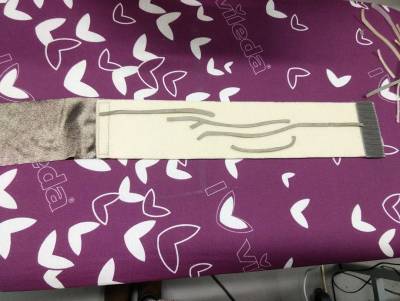

When the traces were in place, I tested the connections with a multimeter and realised that I needed to reinforce the connection at the junctions (ie between the traces and the velcro and the fabric sensor). I therefore sewed in more connections with conductive thread in these areas.
I then sewed by hand the arduino and vibration motor onto their designated positions on the belt. For the arduino pins that needed to be connected to VCC, GND and the vibration motor, I used conductive thread to ensure they were connected. To make sure that the arduino was secure, I added more stitches around the other edges using normal thread.
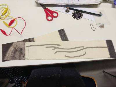
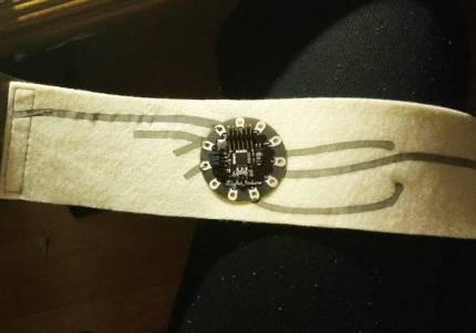
Because I had misaligned the traces slightly when ironing, I had to add a path for the vibration motor with conductive thread. I also hadn't planned fully how the belt was going to be connected to external power in order to be portable. Adriana helped me to realise that the vibration motor needed 5V to operate and the arduino operated at 3.3V. Therefore I needed to use an external battery that provided 5V and I also needed a step down voltage regulator for the arduino to step down to 3.3V.
To make this work, I connected the Vout of the voltage regulator to the VCC of the arduino, the ground to to both the ground of the arduino and also the ground of the external battery, and the Vin to the power of the battery. I had to turn the one ground connection from the voltage regulator into 2 connections to go to the arduino and external battery, therefore I soldered wires together in a 'T' formation and covered the soldered junction with heat sealable rubber.
I placed the voltage regulator and battery in the best place on the belt and created pockets for them. I connected the GND and the VCC wires of the regulator to the arduino using conductive thread. I had to sew an extra path for the VCC as I hadn't planned this in the Rhino design.
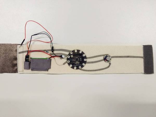
Finished design
Finally the design was complete:
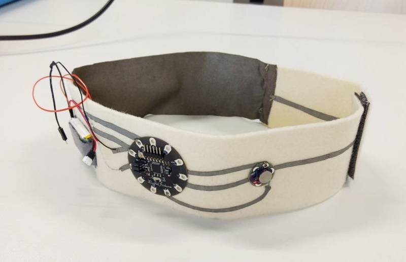
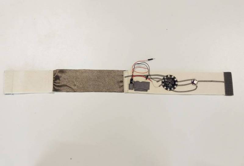
The belt worked successfully when worn - the video below shows the serial monitor displayed the sensor value and reaching the threshold figure. Although it is not perceptible in the video, the back of the belt vibrated as intended.
Problems
I already mentioned the problem of unplanned power supply and step down voltage. In hindsight, I should have used a different a microcontroller that operated with 5V, like the vibration motor, so that I would not need a step down voltage regulator and all the cumbersome wires that came with it. The design would have been cleaner without this.
Final thoughts
This was my first time working properly with arduino, sensors and actuators, and it was very pleasing to have designed a finished product that works.
