Class 9 : e-textiles-wearables2
Silicone Hybrid Fabric Sensor
Material
- Knit conductive fabric Adafruit
- Silicone Smooth-on SORTA-Clear™ 37
- Silicone Smooth-on Mold Star™ 16 FAST
- Silicone Smooth-on Ecoflex™ 00-30
Project Description
Create an interactive object; if you are already experienced with coding, focus on fully integrating a microcontoller into a textile circuit. If you are new to coding, choose an example and get it working using your own sensors and actuators. * Build your own soft actuators and sensors * Integrate them in a working project * Document what you did * Include all source files
Inspirations & References
Hybrid Sensor Fabrication
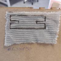
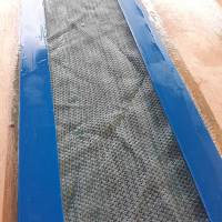
1/cut conductive fabric
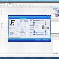
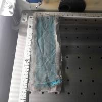
With Epilog Engraver, you can choose to cut with CO2 or Fiber. The best result with metal is fiber. Settings after several tests : speed : 6 / Power : 100 / Frequence : 50 with Autofocus.
The conductive fabric is glued with adhesive spray on wood board, so it doesn't move during cutting.
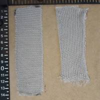
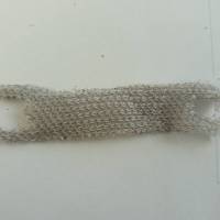
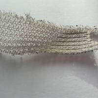
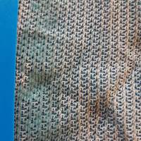
After several tests, the fabric frays and is no longer strong enough
the fabric must be cut wide enough so that it remains strong with its extensions
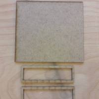
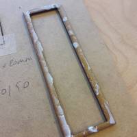
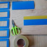
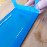
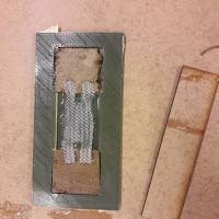
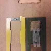
2/cut wood applicator and 1mm plastic applicator
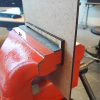
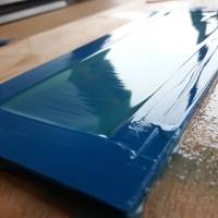
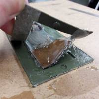
the first silicone applicator was 3mm to pour silicone onto the conductive fabric. The cutting first part is glued into the wood support and held with clamp.
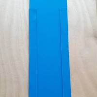
The second applicator with acrylic is 1mm, the thinner thickness should be a more flexible sensor.
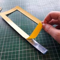
The cutting first part is fixed into the support with double-sided tape.
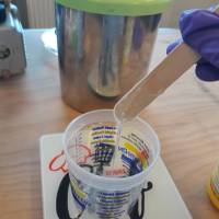
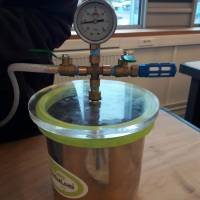
3/Silicone mix in vacuum machine
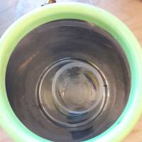
Silicone have to put into the vaccuum machine to remove the air. After mixing parts A and B, vacuum degassing is recommended to eliminate any entrapped air. Vacuum material for 2-3 minutes (29 inches of mercury), making sure that you leave enough room in container for product volume expansion.
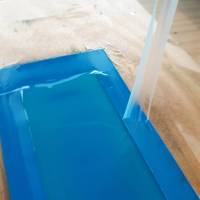
4/pour silicone into the wood applicator and 1mm plastic applicator
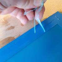
to apply a uniform coat, scrape from top to bottom with equal pressure.
Several silicone tests have to be done for testing flexibility. The ecoflex in the acrylic applicator give a really thin film and a good flexibility thanks to its shore hardness of 00-30.
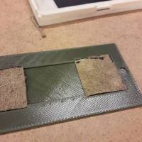
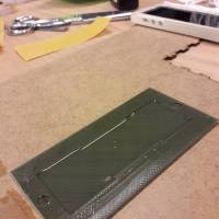
5/pour silicone into the first 3D printed PLA applicator by Romain Di Vozzo
7/let it dry for 4 hours
the drying depends of the cure time of the silicone. For ecoflex is 4 hours.
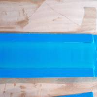
the excess silicone on the edges is removed to allow a better adhesion to the second part of the mold
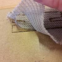
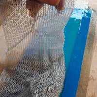
8/put the piece of fabric
9/pour a second silicone layer
apply the second silicone layer using a mould of the same thickness as the first one. Repeat scrape from top to bottom with equal pressure.
10/hybrid sensor observations
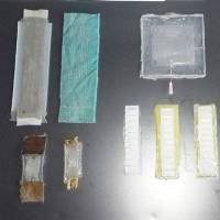
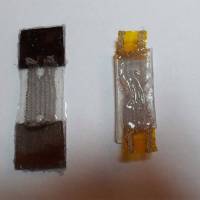
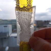
The 4 sensor are on left part of the picture
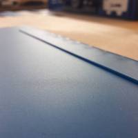
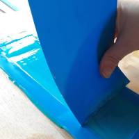
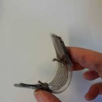
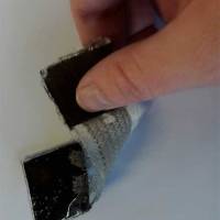
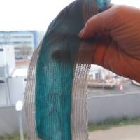
The sensor is released from its mold, with ecoflex we can see a really good flexibility and with pieces of leather a stretchy and strong sensor
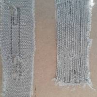
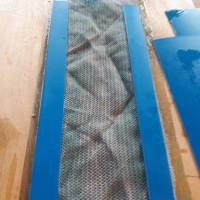
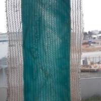
Compare to the left sensor, the right sensor : the fabric is not flat into the silicone and the layer is thicker so less flexible
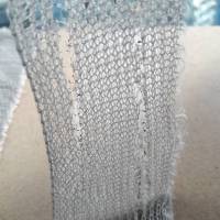
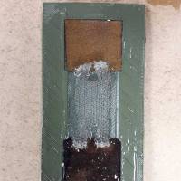
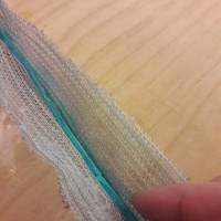
On this one the fabric is wrinkled and the silicone layer too thick with a more important shore
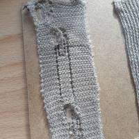
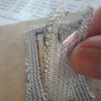
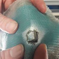
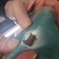
a cutting test is performed to see if it is possible to cut once the sensor is finished : but cutting fabric with metallic fibers on this thickness and silicone damages the sensor too much.
film applicator for silicone sensor molding
find the romain Di Vozzo's files on https://www.youmagine.com/designs/film-applicator-for-silicone-sensor-molding The final sensor was done with this applicator, the conductive fabric is best quality with silicone ecoflex the sensor is very wrinkleable, stretchable and flexible. without the machine vacuum you can see some dried air bubbles on both sides of the sensor.
Arduino tests
connect an analog sensor to the Arduino
See the instructable here : [http://www.instructables.com/id/Connecting-a-textile-analog-sensor-to-Arduino/|Connecting a Textile Analog Sensor to Arduino]]
- Connect the '+' pad of your Lilypad to your sensor. Sensors are not polarized, so it does not matter on which side you connect it.
- Connect the output of the sensor to the analog input a0 of the Lilypad
- Connect Sensor to Ground.
Plug the USB cable into your USB port of your laptop, and into the USB port of the FTDI board and copy, paste and upload the following program to the Lilypad:
int softPot = 0; // this line selects the input pin a0 for the sensor
int ledPin = 13; // this line selects the pin 13 for the LED output
int tempPot = 0; // variable to store the value coming from the sensor

void setup() {
// this line declares the ledPin as an OUTPUT:
pinMode(ledPin, OUTPUT);
}

void loop() {
// read the value from the sensor and store the value in the variable tempPot
tempPot = analogRead(softPot);
// it turns the LED on
digitalWrite(ledPin, HIGH);
// stop the program for milliseconds:
delay(tempPot);
// turn the LED off:
digitalWrite(ledPin, LOW);
// stop the program for for milliseconds:
delay(tempPot);
}
upload the sketch into the lilypad and open the monitor we can see the voltage variation between O (the sensor is not stretched) and different more or less intense variations (if the sensor is stretched, twisted, bent…)
