Table of Contents
E-textiles and Wearables I
Assignment
The students will have to produce one soft sensor experimenting with the materials available at the lab. Trying to reproduce the same sensor with different materials/techniques (hard/hard hard/soft soft/soft).
How will it be evaluated?
- (Done) Student has built on or more soft sensors, using different materials and techniques
- (Done) Student has provided necessary documentation to replicate the project
- (Done) Source files available for download
Files
All the files created for this assignment can be downloaded by clicking on the link bellow:
Designing Patterns for the Soft Sensor
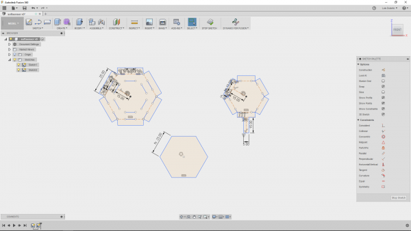
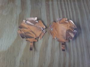
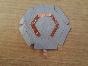
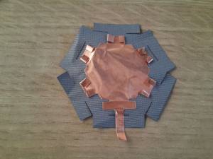
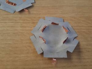
The sensor I wanted to do was a pressure sensure. So I needed a fabric sensitive to pressure a couple of contacts and a cover for the sensor. So I decided to design the sensor so that it used soft connections. The contactcs were designed so that they were attached to the cover by tabs. And the sensor was closed also with tabs. The pressure sensor was designed without tabs so that it were between both contacts inside the closed sensor. The design was done in Fusion 360.
Once, I finished, I exported the sketch in a dxf file.
Fabricating a Pressure Sensor
Fabricating Contacts
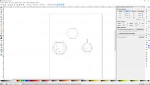
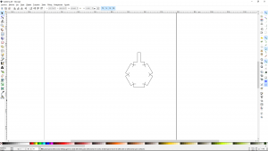
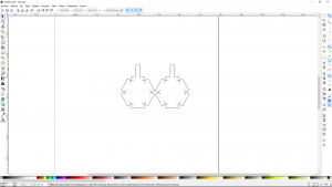
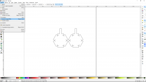
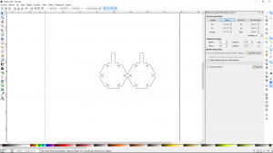
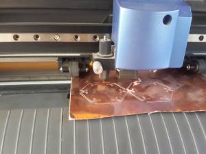
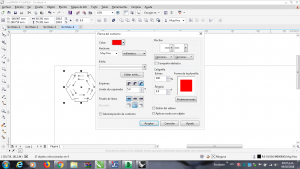
So, I needed to cut copper for the contacts in a vinyl cutter and pressure fabric and the nylon (for the cover) at a laser cutter. So, I modified the exported file with inkscape software so that I had only a couple of contacts on the file and then exported the file as a png file.
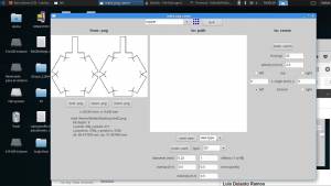
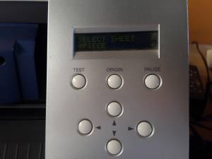
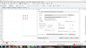
Then I used the fab modules software for cutting on the vinyl cutter.
Fabricating Cover and Inner Pressure Fabric
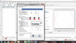
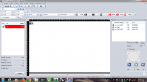
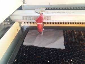
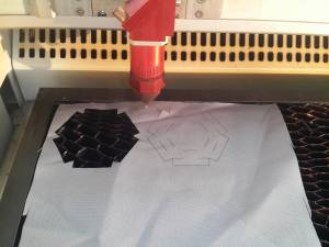
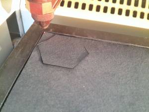
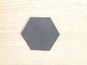
I made the cover of Nylon, so I used nylon as an input parameter on the trotec software while for the inner presssure fabric I used as an input parameter denim, just to ensure that the laser will cut it.
Assembling the Sensor
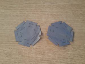
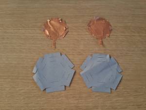
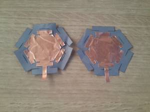
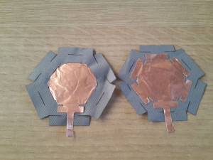
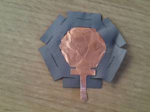
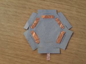
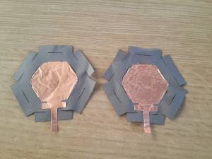
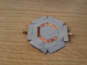
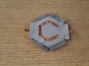
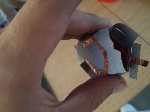
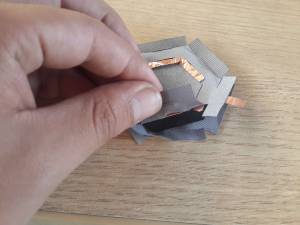
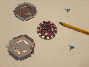
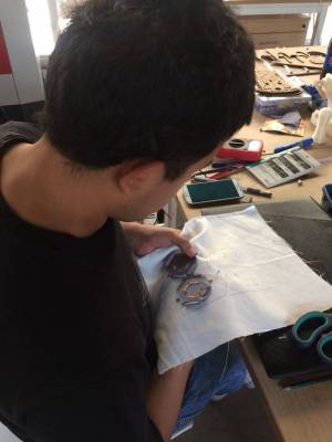
Once I had all the pieces, I assembled the sensor, the steps can be seen on the images bellow.
Making a Soft Circuit
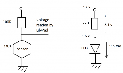
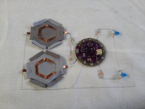
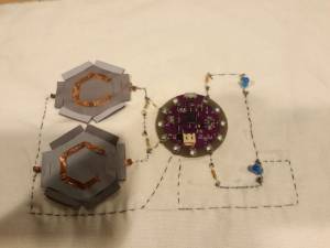
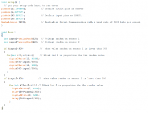
The circuit I made consists on making a voltage divider with a pressure sensor and the read the voltage on the sensor with a lilypad by its analog pin. I fabricated and integrated a second sensor on the circuit, so that when the sensor 1 wass pressed the led 1 controlled by the lilypad will blink as much as the sensor 1 was pressed, while if the sensor 2 was pressed the led 2 blink as much as the sensor 2 was pressed.
When the sensor was not pressed it a had a resistance of 330 kOhms so I looked for a resistance that was in the order of hundreds of kOhms for doing the voltage divider. So i selected a 100 Kohms resistance. While for the leds, they needed between 10 mA to 20 mA through them. So, I looked for a resistance that will gave 10 mA for a 3.7v source. The lowest resistance I had was of 220 Ohms, and assuming that the votage on the led was of 1.6 v, I got around 9.5 mA ((3.7v-1.6v)/220) through the led.
Programming the lilyPad
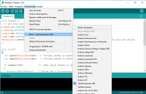
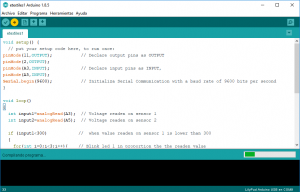
For programming the Lilypad, I used the arduino software. I wrote the code, and then selected on Tools the board LilyPadUSB (the one i was using) and then just clicked on upload.
This is the resulting circuit:
