This is an old revision of the document!
Skin Electronics
Assignment
- (Done) Use one of the project’s option (carnival masks or tech nails).
- (Done) Personalize it with your project: change/add electronics (LEDs, acceremoter, etc).
- (Done) Improve the design: change the colors, add some crystals or other 3D elements.
- (Done) Presentation: explain your motivation and how you personalized your project.
Files
All the files created for this assignment can be downloaded by clicking on the link bellow:
General Idea
The idea I had was to use the tech nails for playing musical notes on an speaker and thinking that people that hear me won't know what notes I am playing I added some leds to show which musical note was played.
Working with RFID
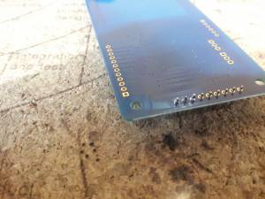
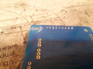
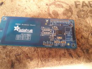
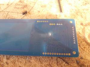
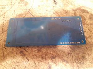
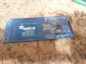
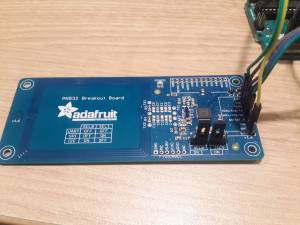
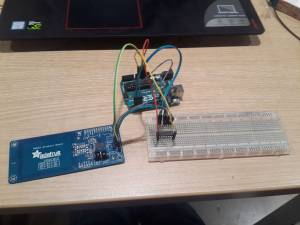
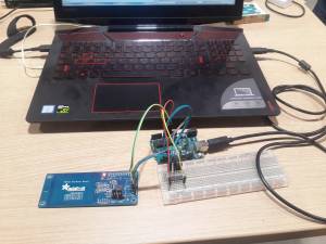
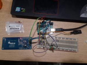
I worked with the PN532 breakout board and three RFID tags. The board came without pins soldered, so I had to soldered them. So once I soldered them, I made some connection for communicating the board with an arduino uno.
The communication on the board is specified on its chip selectors SEL0 and SEL1 and since I planned to use the SPI protocol for communication, I needed to to put a jumper in ON position on SEL1 and another jumper in OFF position on SEL0.
Since the Arduino works with 5 volts and the PN532 board with 3.3v, I had to connect a buffer that lowered the voltage of the arduino to 3.3v, so that it did not burn the PN532 board. The buffer I used was the IC4050.
Making an Interactive Circuit
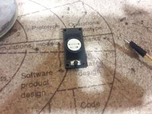
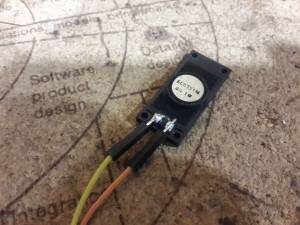
For making the circuit I wanted, I had to add three leds to the outputs of the arduino and an speaker. So, I had to solder some cables to the speaker and then added it to the output of the arduino. Both the speaker and the leds can not be directly connected to the arduino sice they have very low resistance and that means a high current can pass through them which could burn the arduino pins. So for limiting the amount of current at the output of each led and the speaker I added a resistance in series to the speaker and since only one of the leds was going to be on when a note was played I added only one resistance in series for the three leds.
Hiding the RFID Tags Inside the Fake Nails
For hiding the RFID tags in the faik nails I did the following:
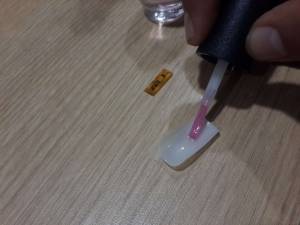
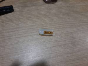
- I took one of the faik nails and added a layer of base coat to the inner side of the nail and waited until it dried (this was done to better the adhesion of the RFID to the nail).
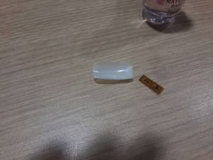
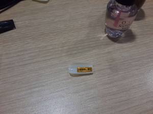
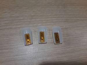
- Then, I putted the RFID tag over the dried layer of base coat.
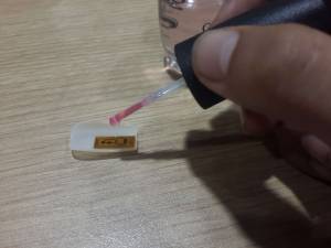
- I added a second layer of base coat over the RFID tag and waited until it dried (this layer sticked the RFID tag to the first layer of base coat).
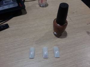
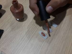
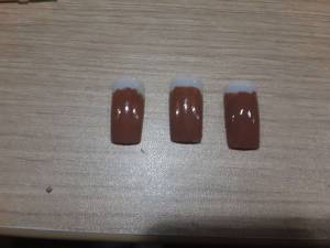
- Afer that, I painted the nail with brown nail lacker, for hidding the RFID tag on the semitransparent nail and waited until it dried.
- I did the steps 1 to 4 for the other two nails.
Programming the Arduino
For working with the Pn532 board, I downloaded a library provided by ardafruit, which can be downloaded from here.
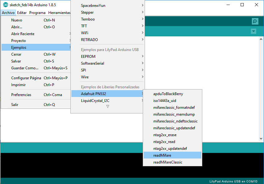
Since I have never worked RFID, I opened the example “read Mifare” provided on the library and started to work from there. I realized that for what i wanted to do I just needed to read the UID of the RFID tags, so I erased almost all the code of the example and kept just the parts that were necessary for reading the UID.
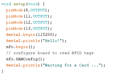
Once, I did that I started to modify the code so that it did what I wanted. First I initialized the serial communication to 115200 bits per second and defined the outputs of the arduino, this were the three leds and the speaker.
Then, I run the code and got the UID of each RFID tag by printing it on the serial monitor. Once I got them, I saved them as arrays on my code and then modified the code so that it always compared the UID readen with the ones I have stored.

I did this by comparing each block of the UID and summing the number of succesful comparison for each UID; if the number of successful comparisons was equal to the number of blocks on the UID, it meaned that all the blocks were correct and thus that a stored UID was detected.
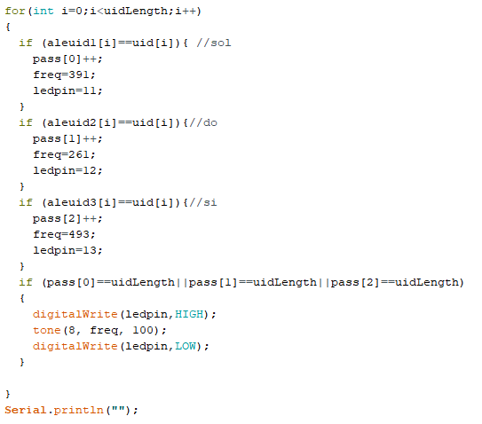
knowing that the last values modified on the code came from the if block of the UID detected, I assigned inside each if block the frequency of the musical note to be played and the number of the pin on the arduino to be set to high for turning on the led. After storing the values I emitted a tone with the frequency stored and set to high the pin specified for turnuning the led on
Just to mention, the musical note for the second UID was DO and for the third one was SI.
The final result can be seen on the next video:
