This is an old revision of the document!
Digital Bodies
Assignment
Use software to obtain a body-figure and a digital fabrication process to produce it (the production happens in groups of 3-4)
How will it be evaluated?
- (Done) document use of a 3D scanner to acquire a model
- (Done) document repair of 3D model mesh
- (Done) experimented with the combination of milling, laser cutting, vacuum forming and composites
- (Done) built your own mannequin
- (Done) include all the files in the documentation
Files
All the files created for this assignment can be downloaded by clicking on the link bellow:
3D Scanning My Self
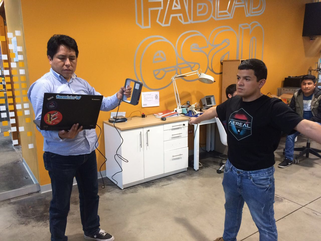
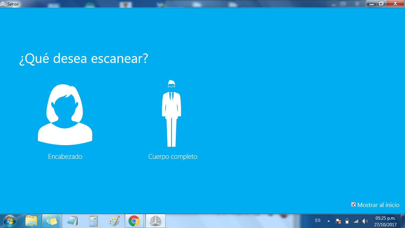
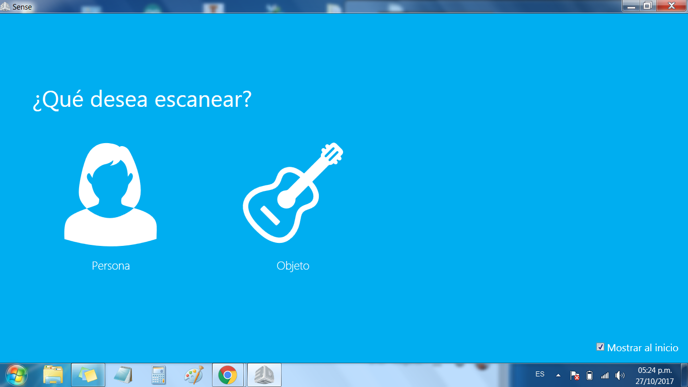
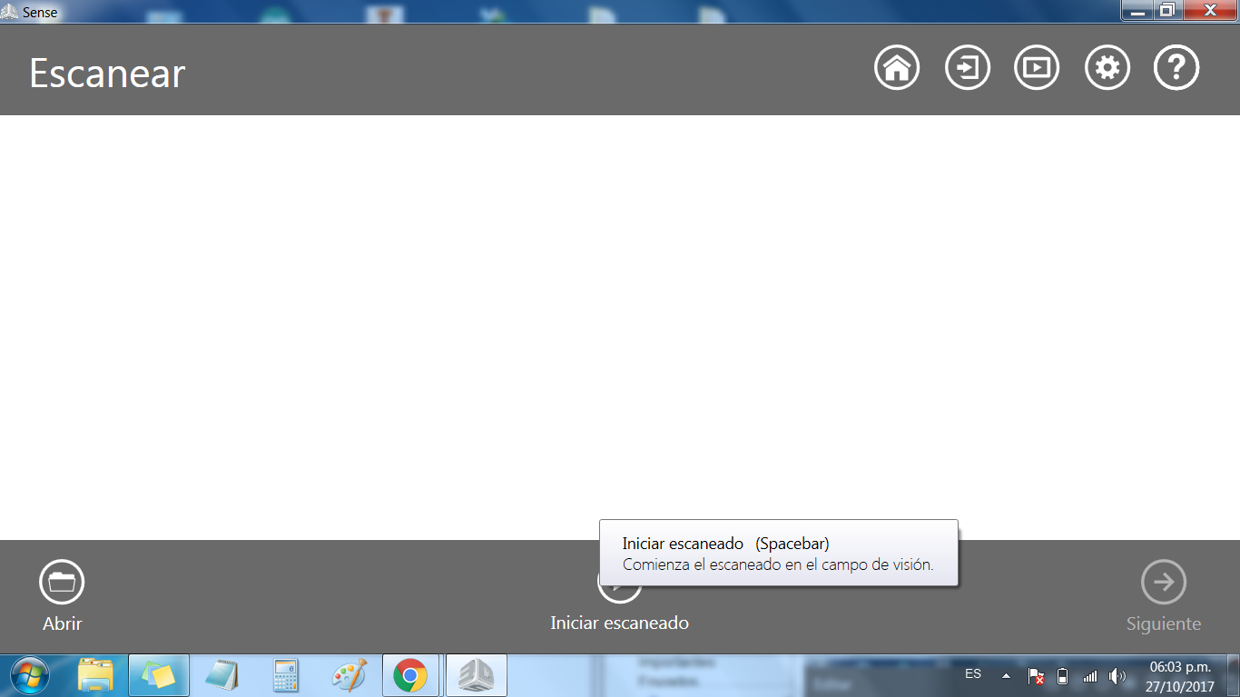
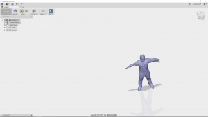
With the aid of my tutor, I got scanned with a Sense 3D Scanner, the use of the software was not complex, the steps I followed through are shown on the images below.
Finally, I exported the body on an STL file.
Working With Mesh Mixer
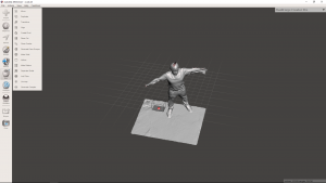
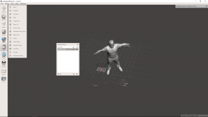
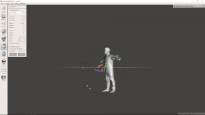
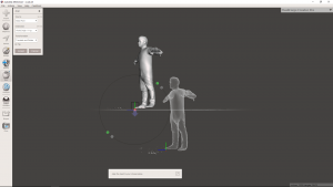
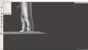
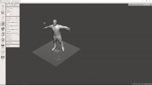
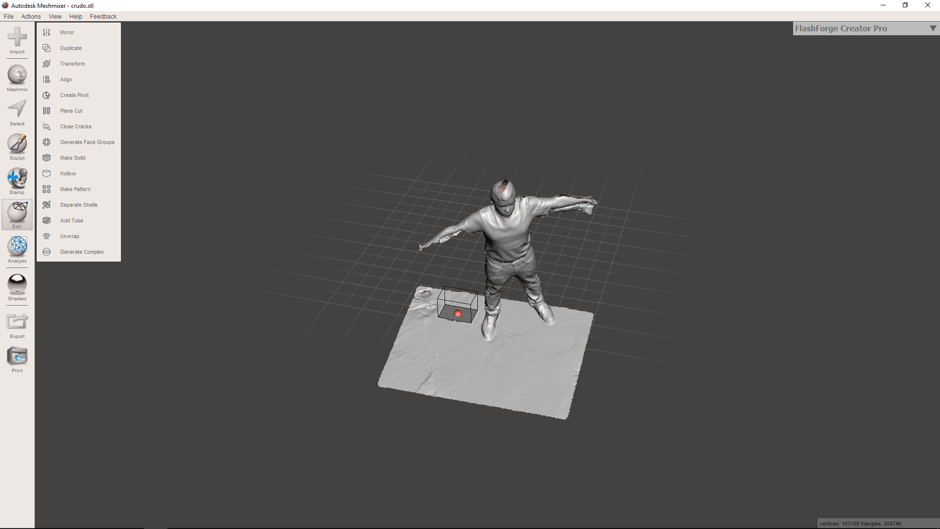
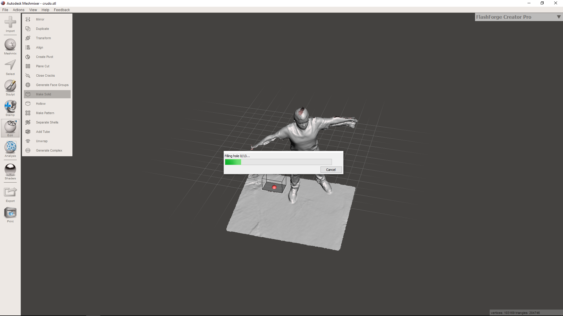
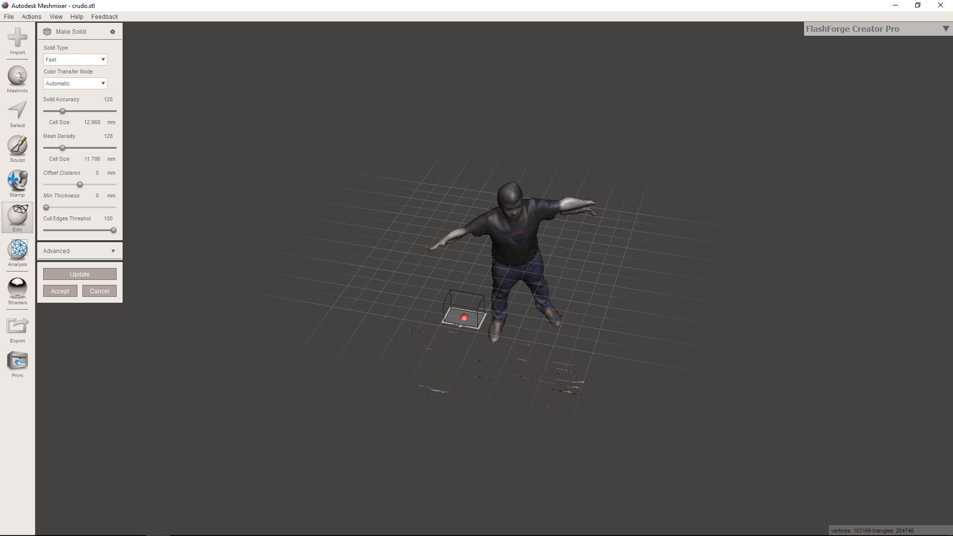
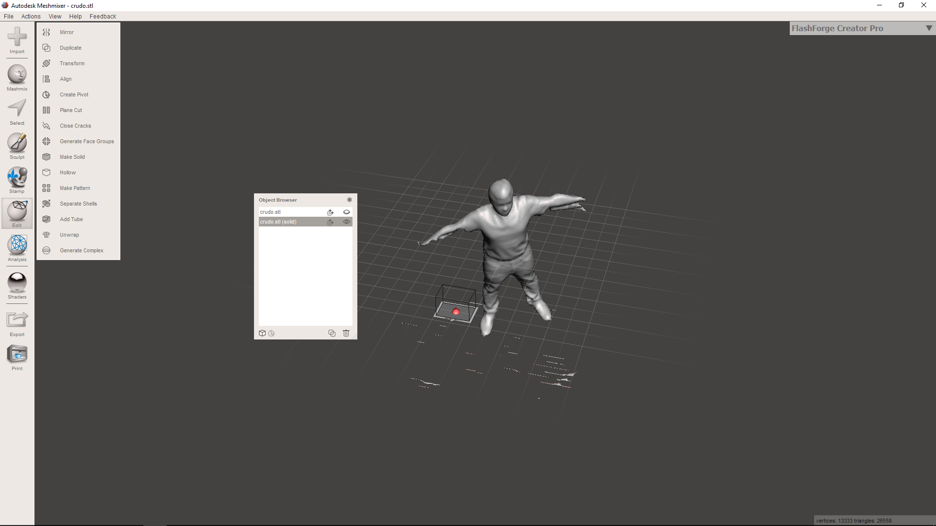
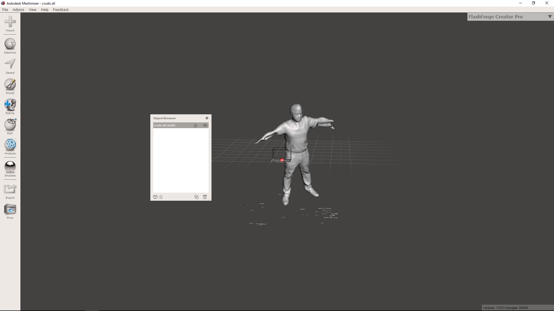
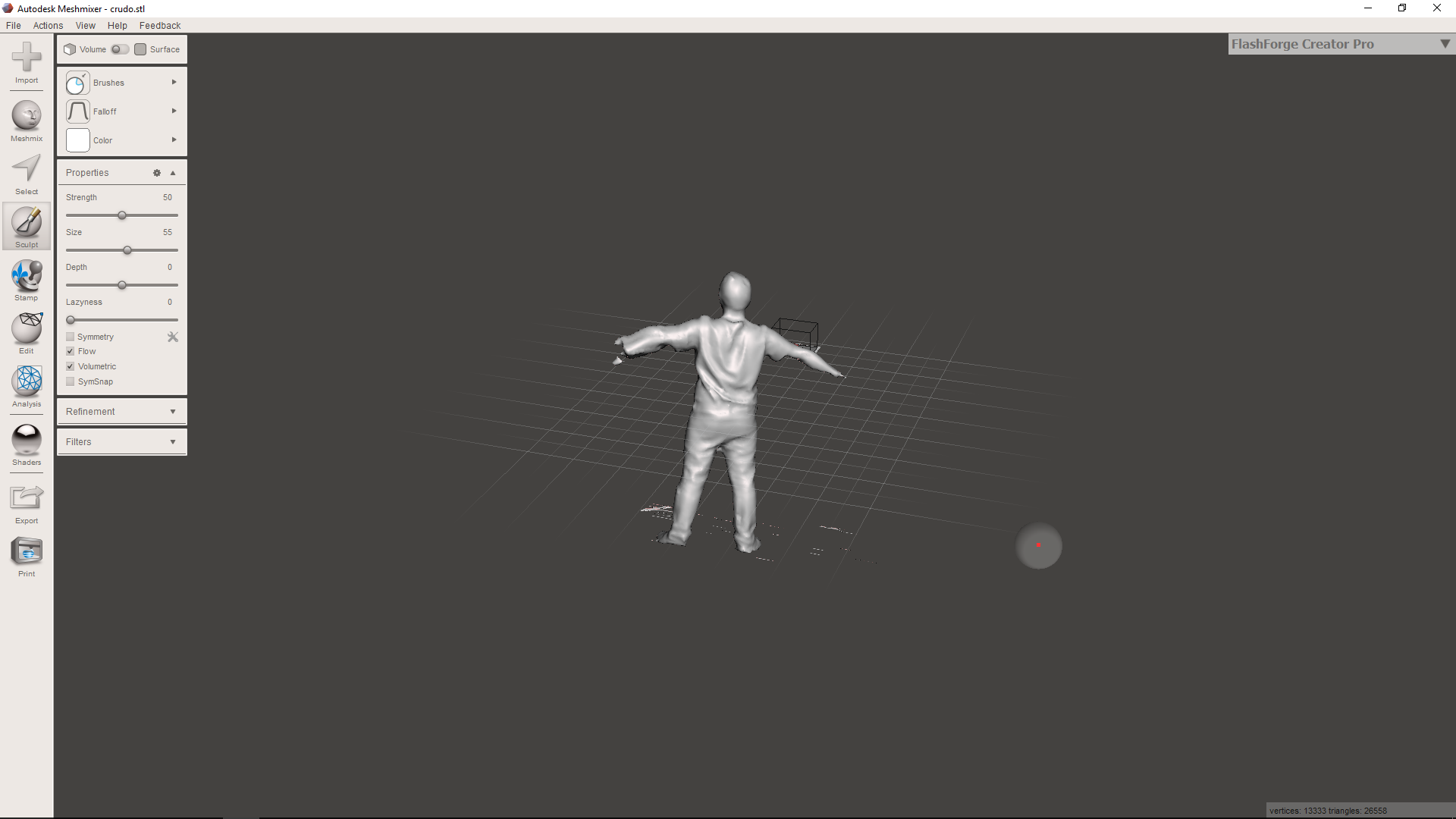
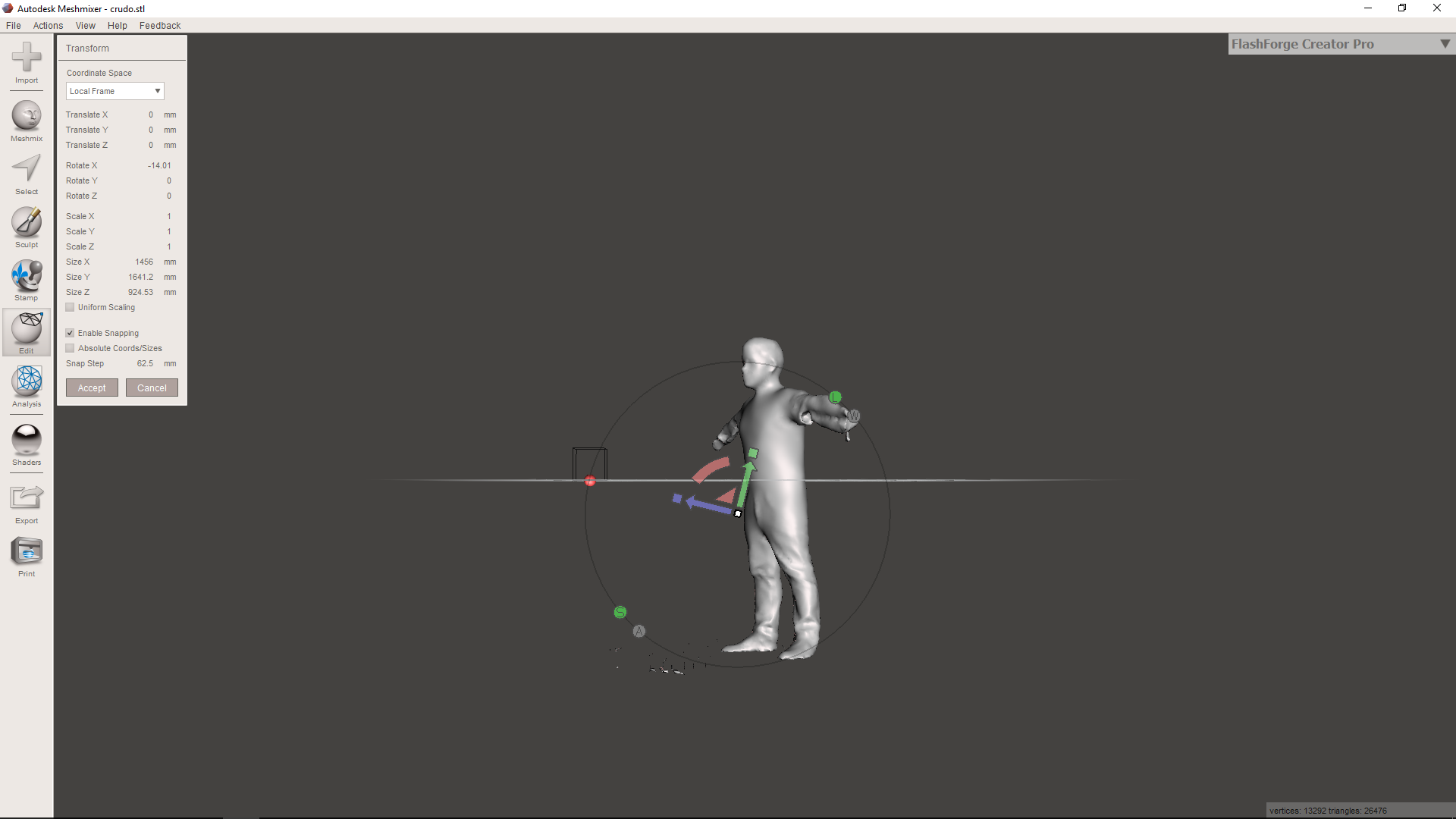
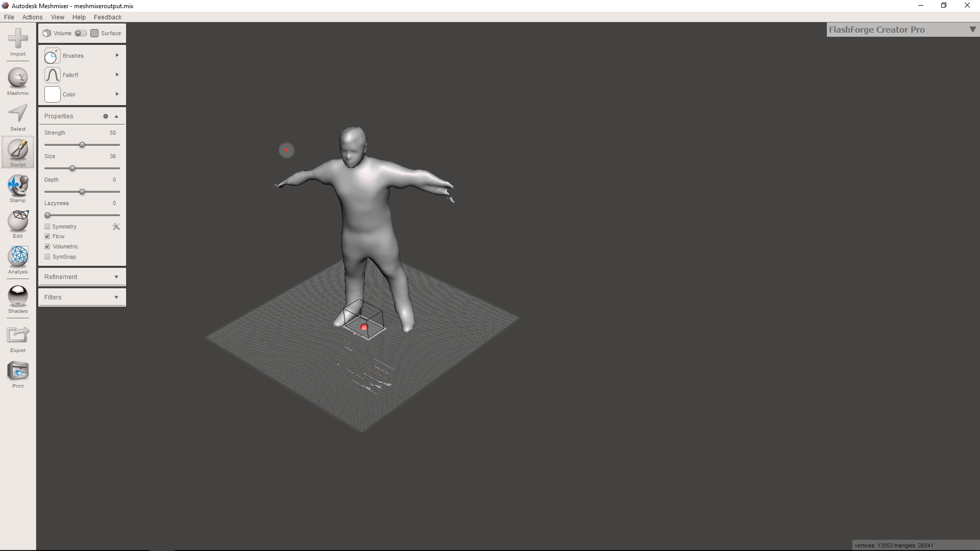
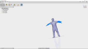
In order to repair the scanning imperfections, I loaded the STL file on the Meshmixer software. I used some filters for correcting the wrinkles on my clothes.
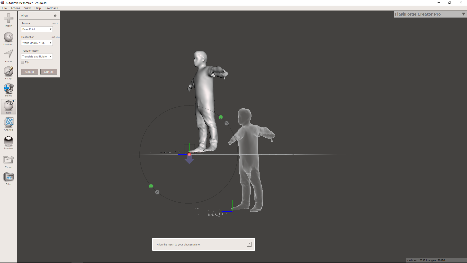
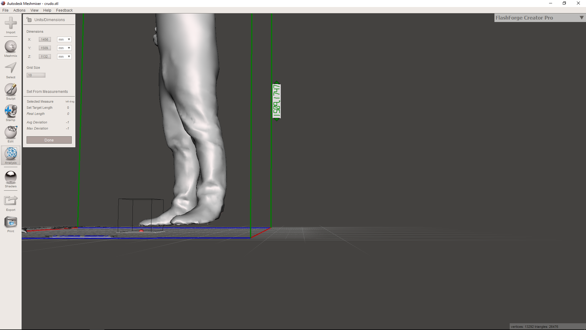
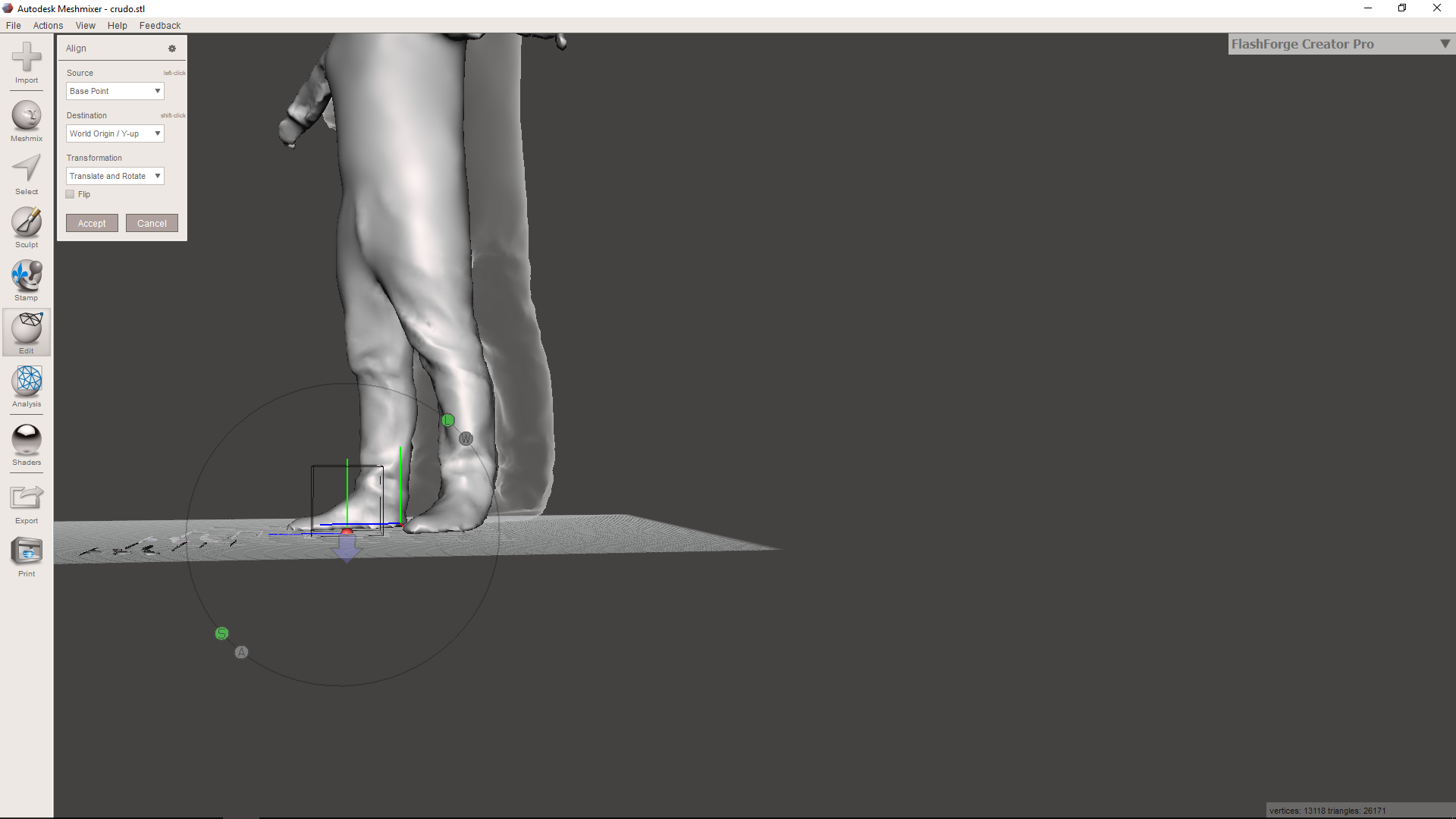
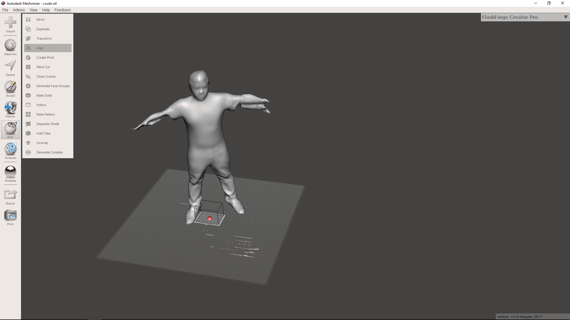
Basically, I made solid the imported stl, applied a shrink smoother for eliminating the wrinkles, then I aligned the base of the body whith the horizontal plane and deleted the residues of the scanning process.
The process followed on the software is shown on the images bellow.
Once again, I exported the corrected body on an stl file.
Working With Fusion 360
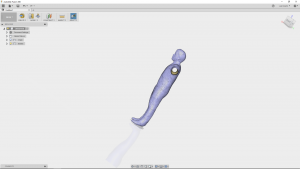
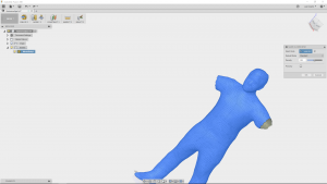
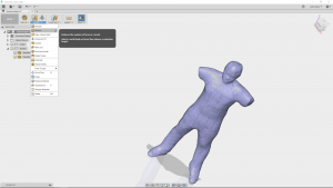
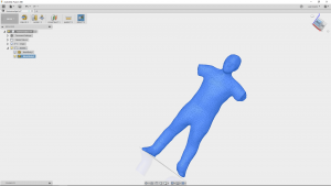
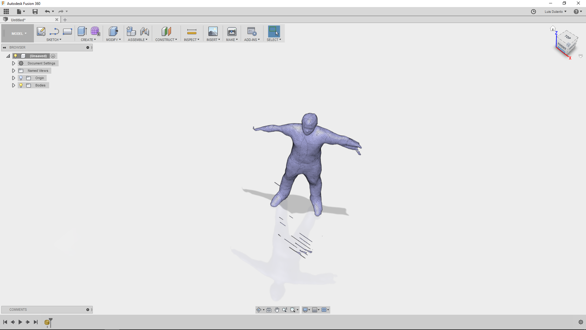
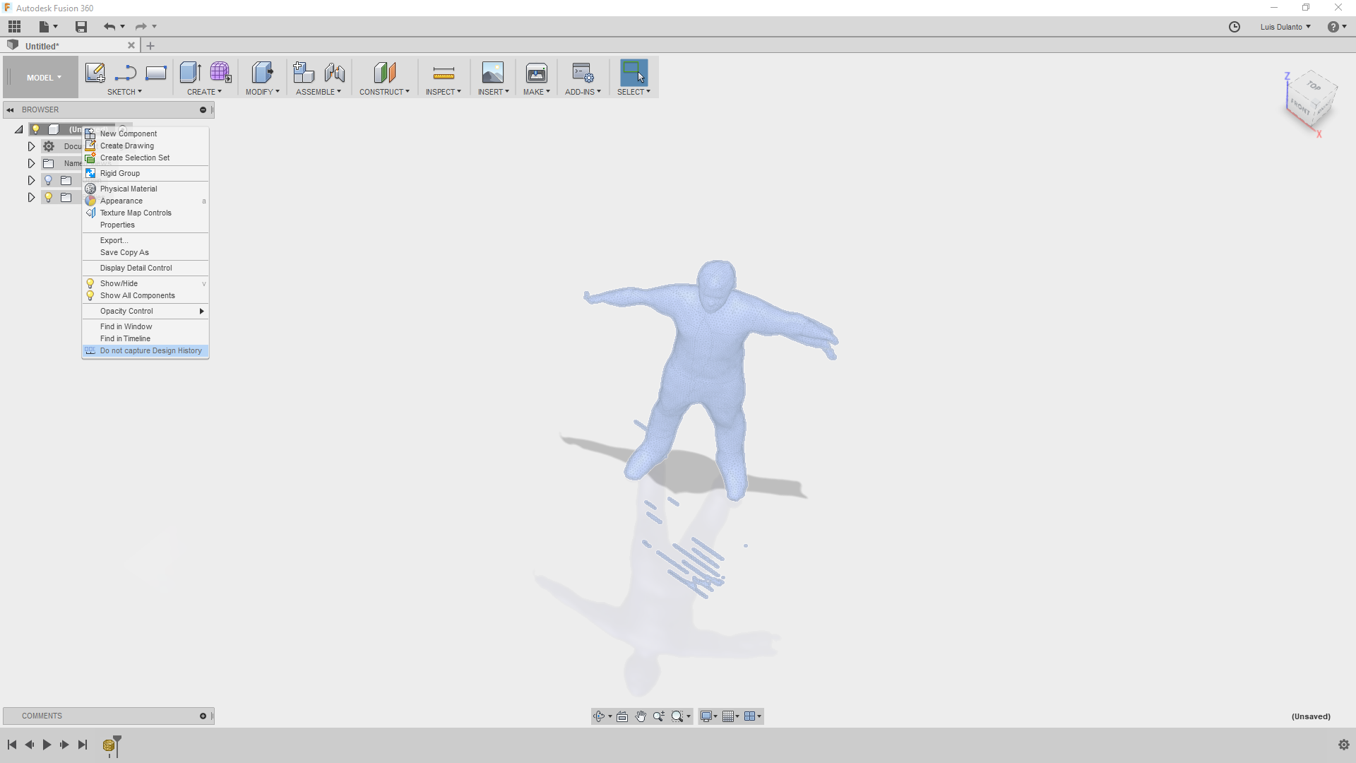
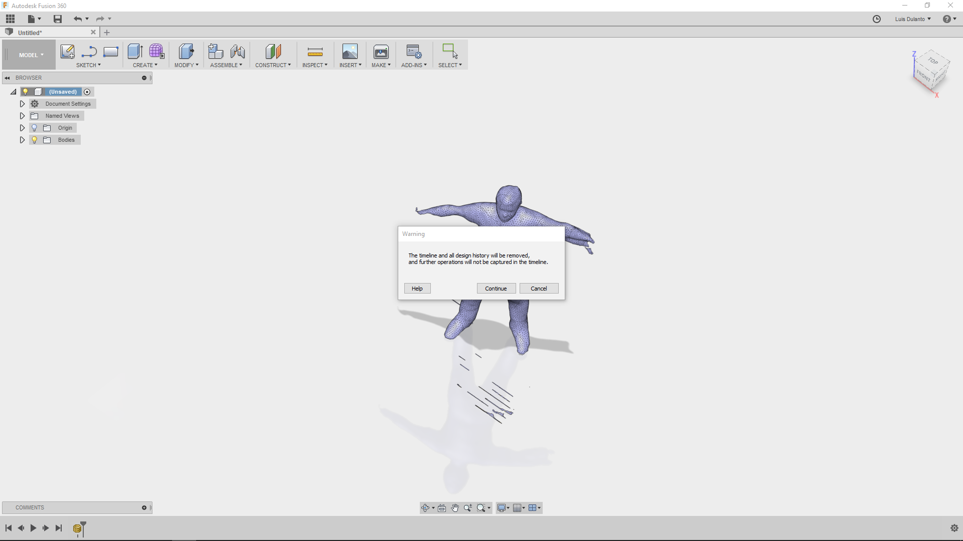
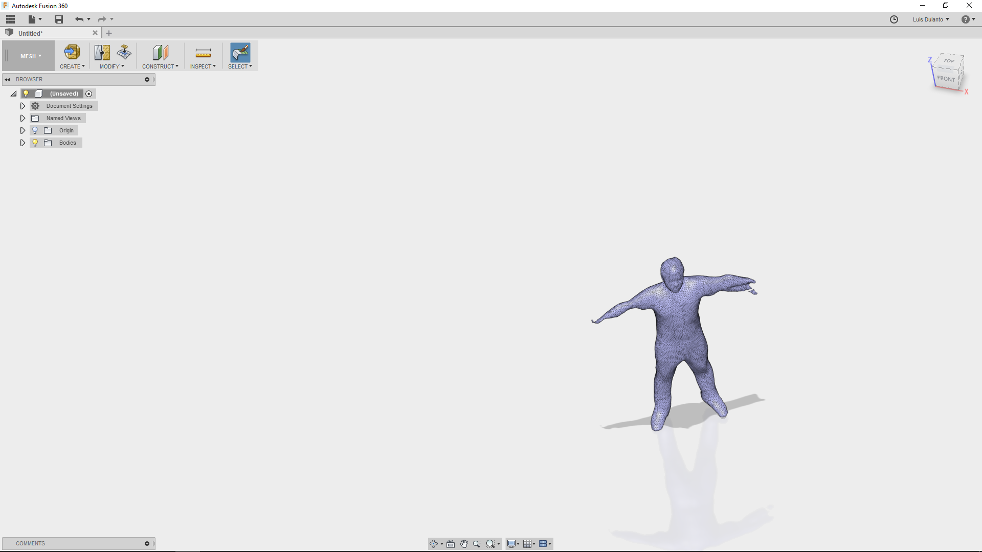
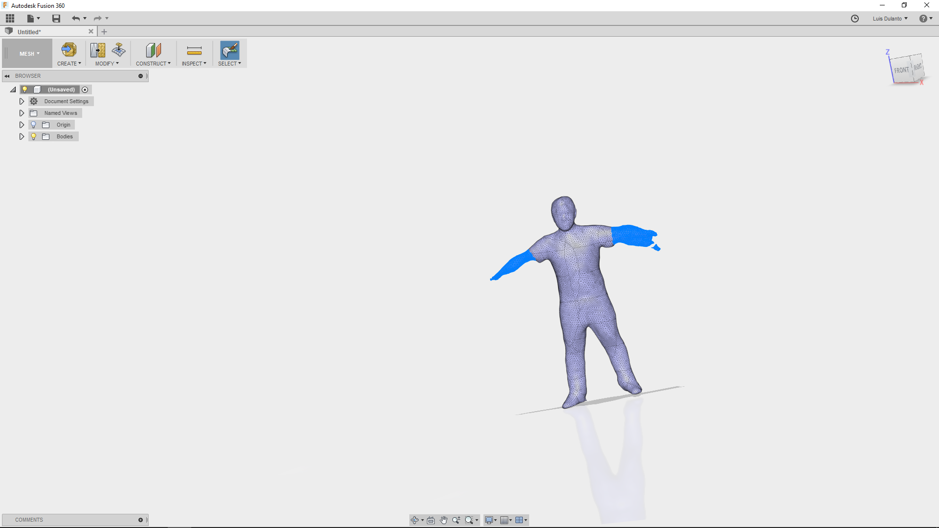
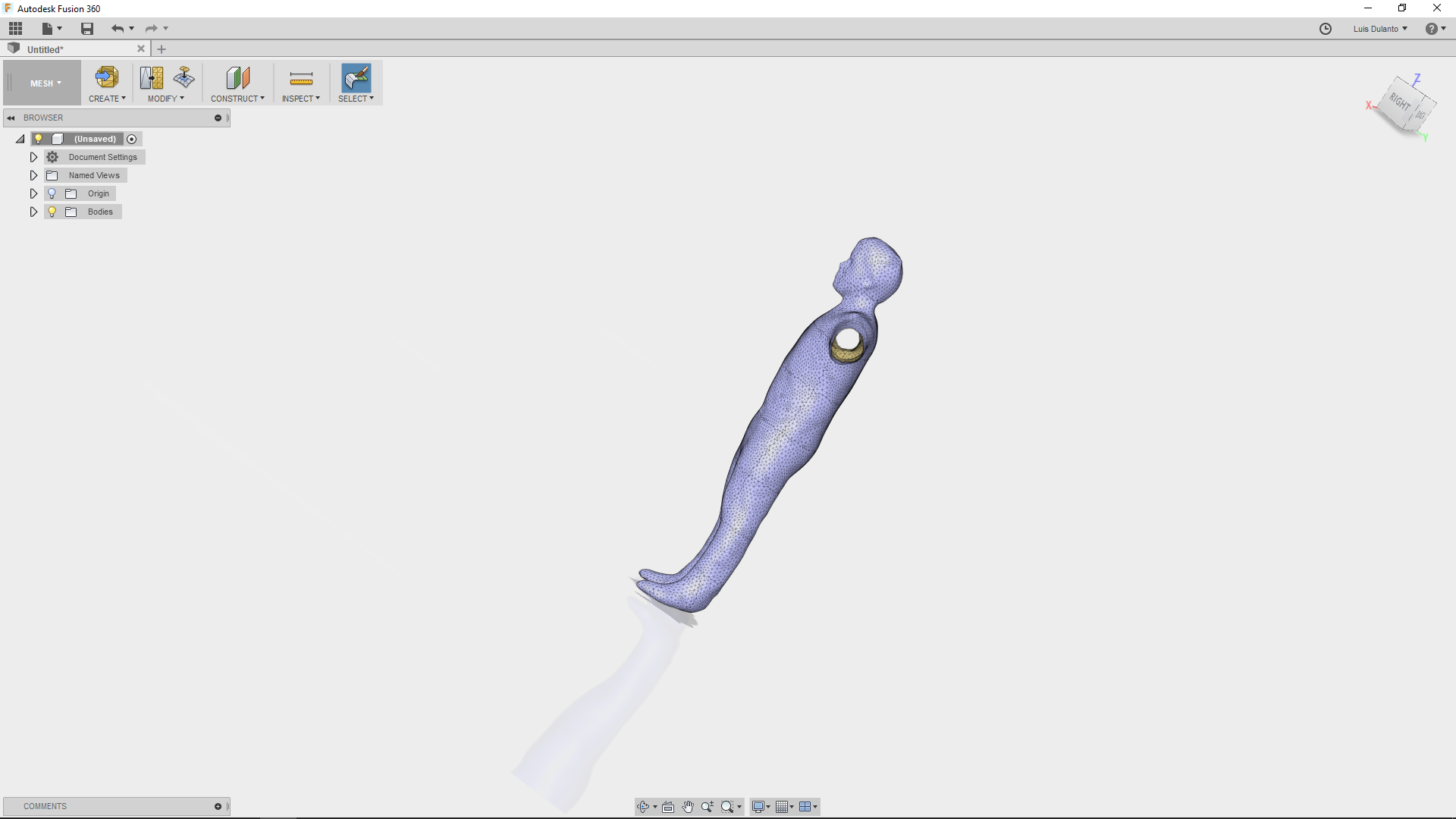
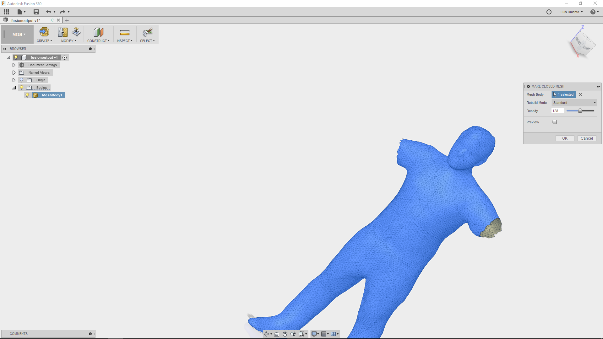
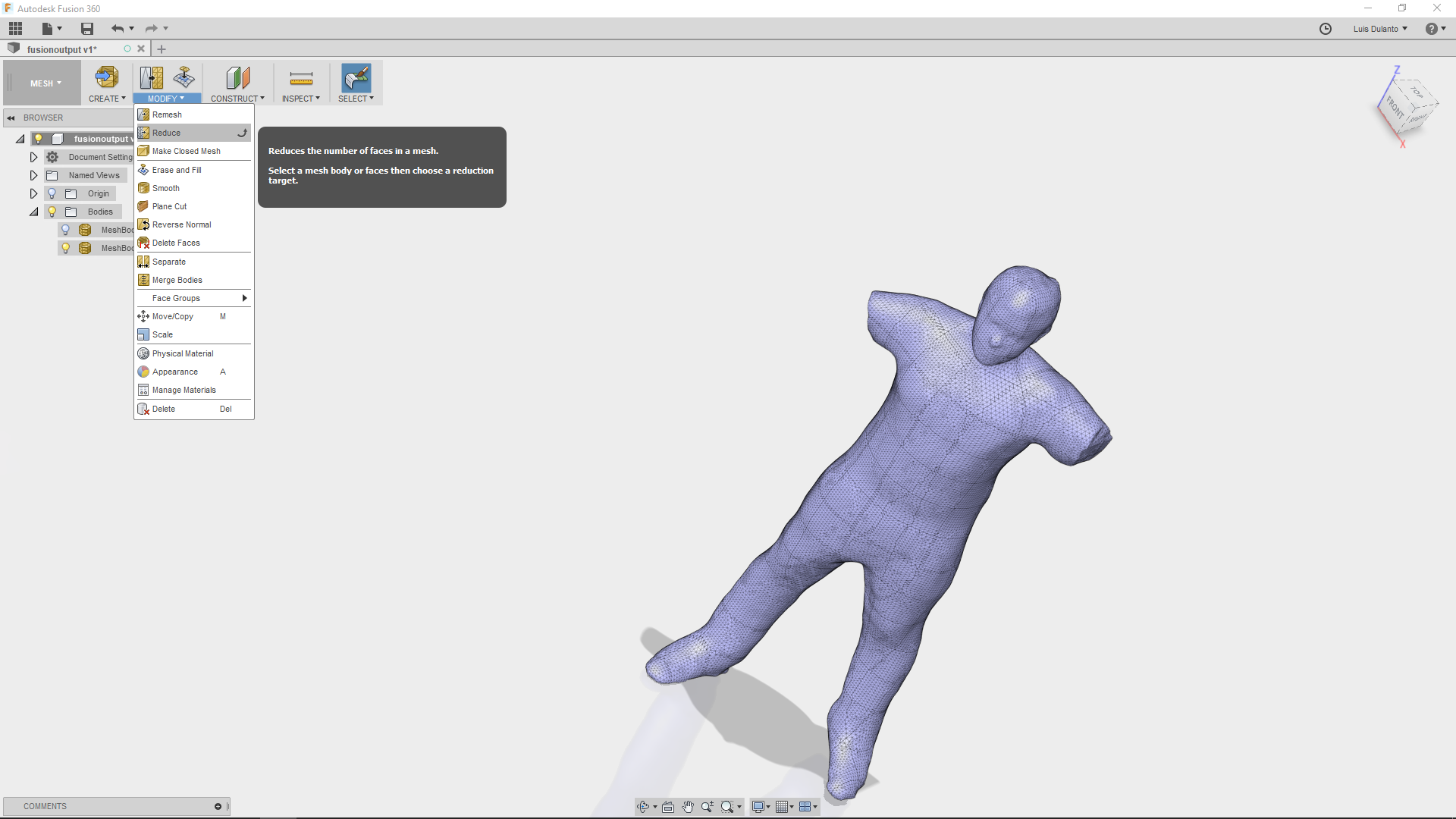
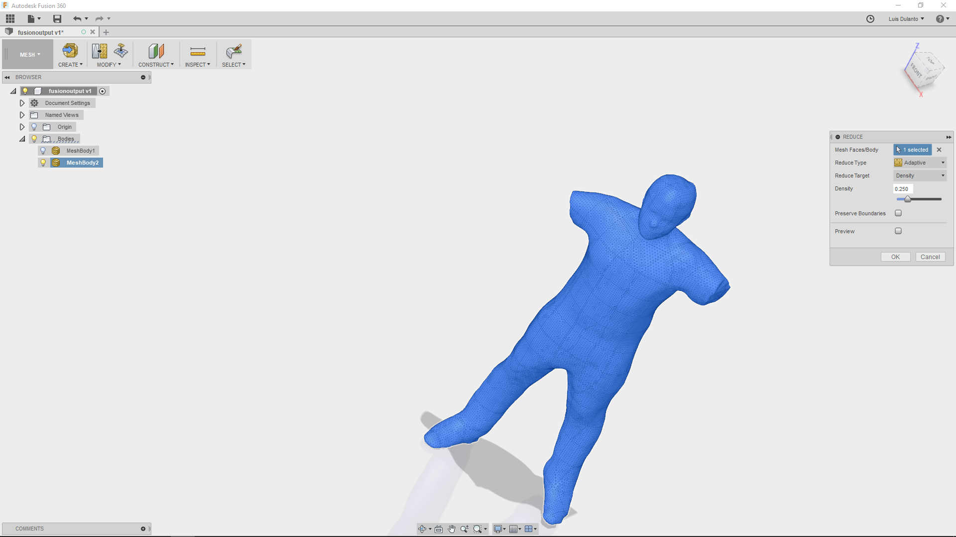
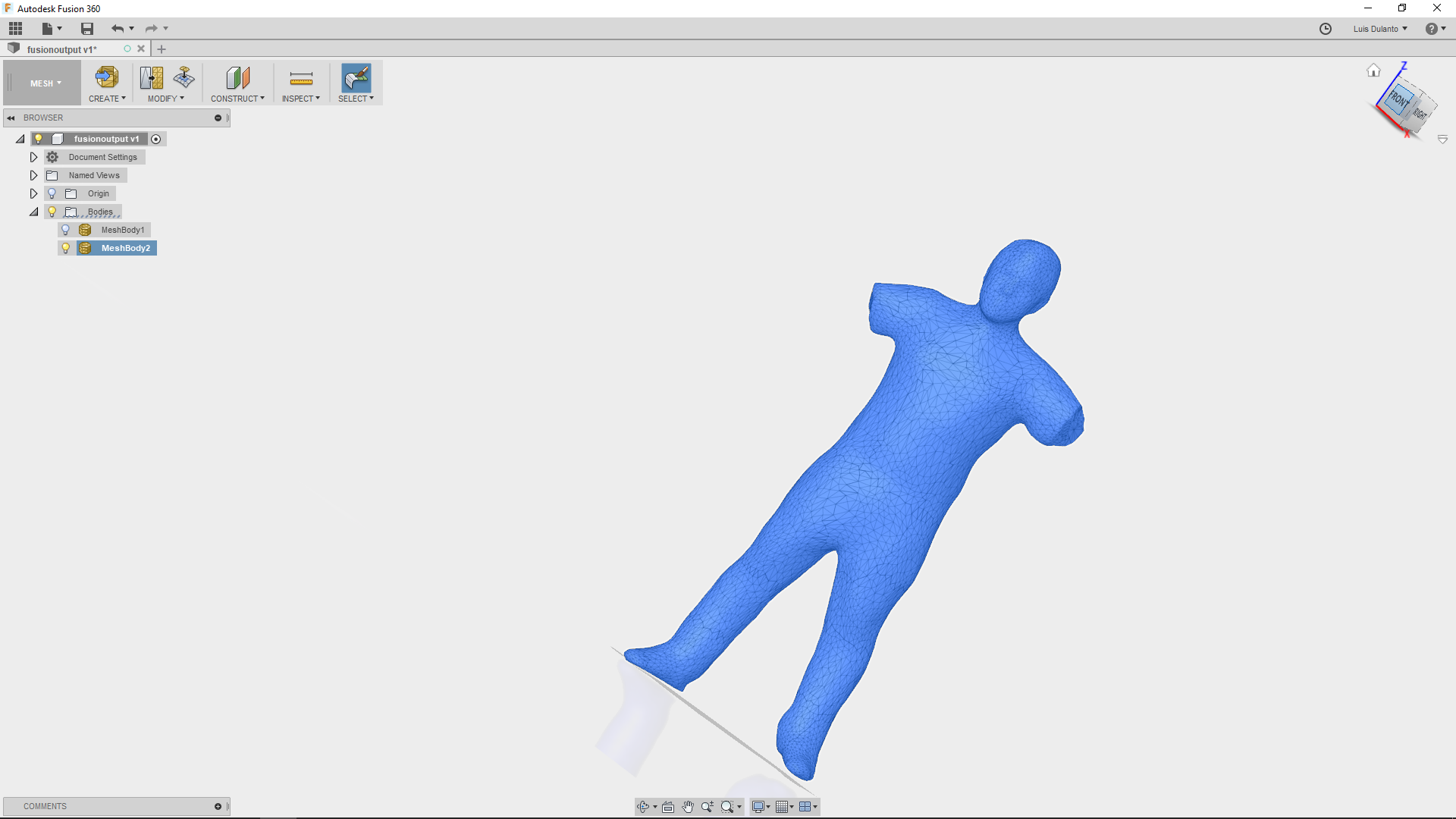
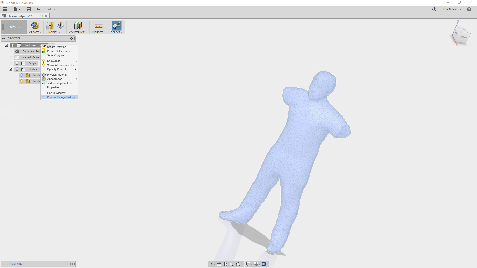
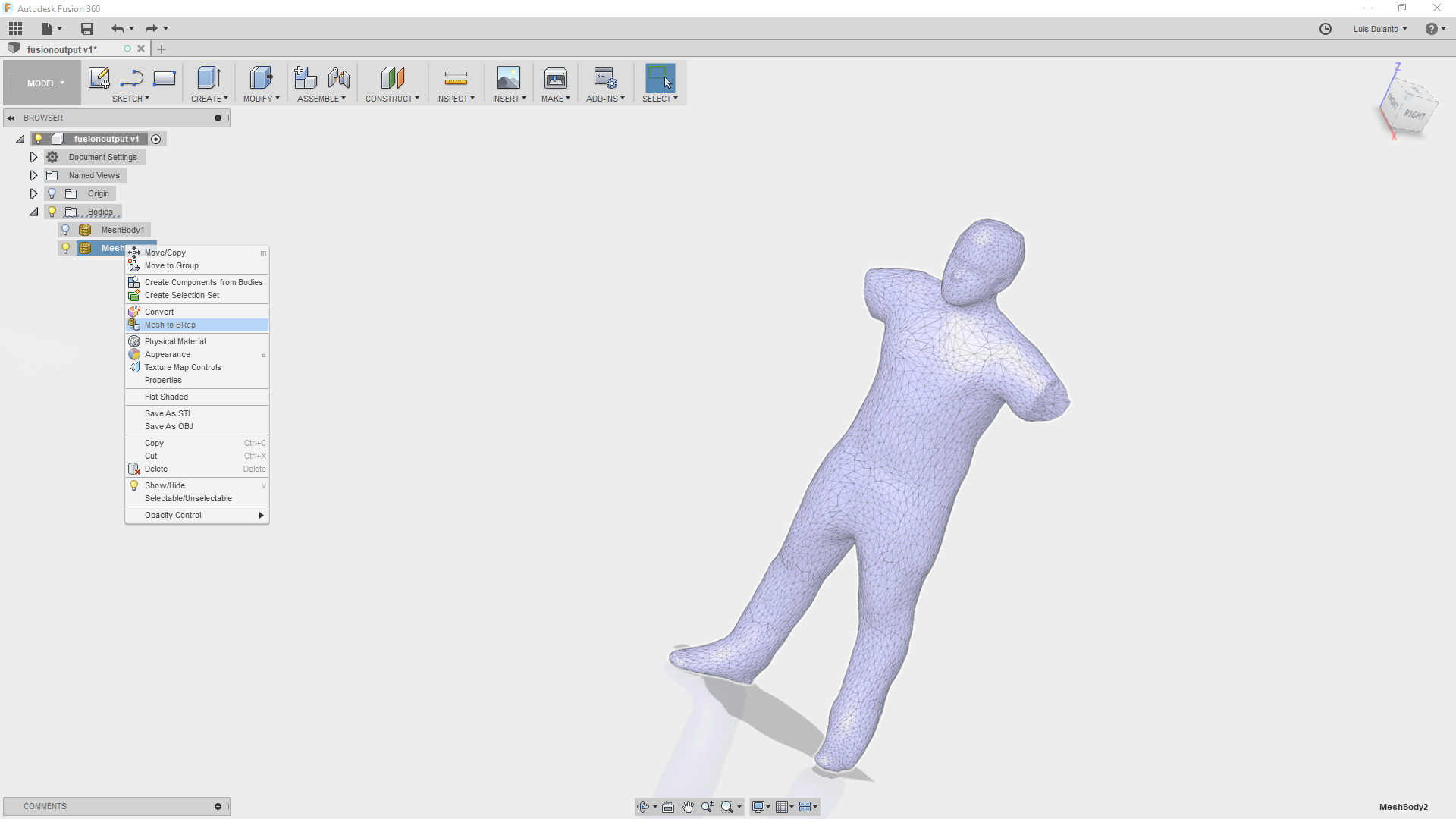
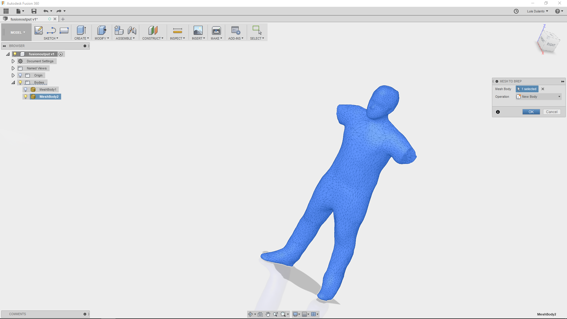
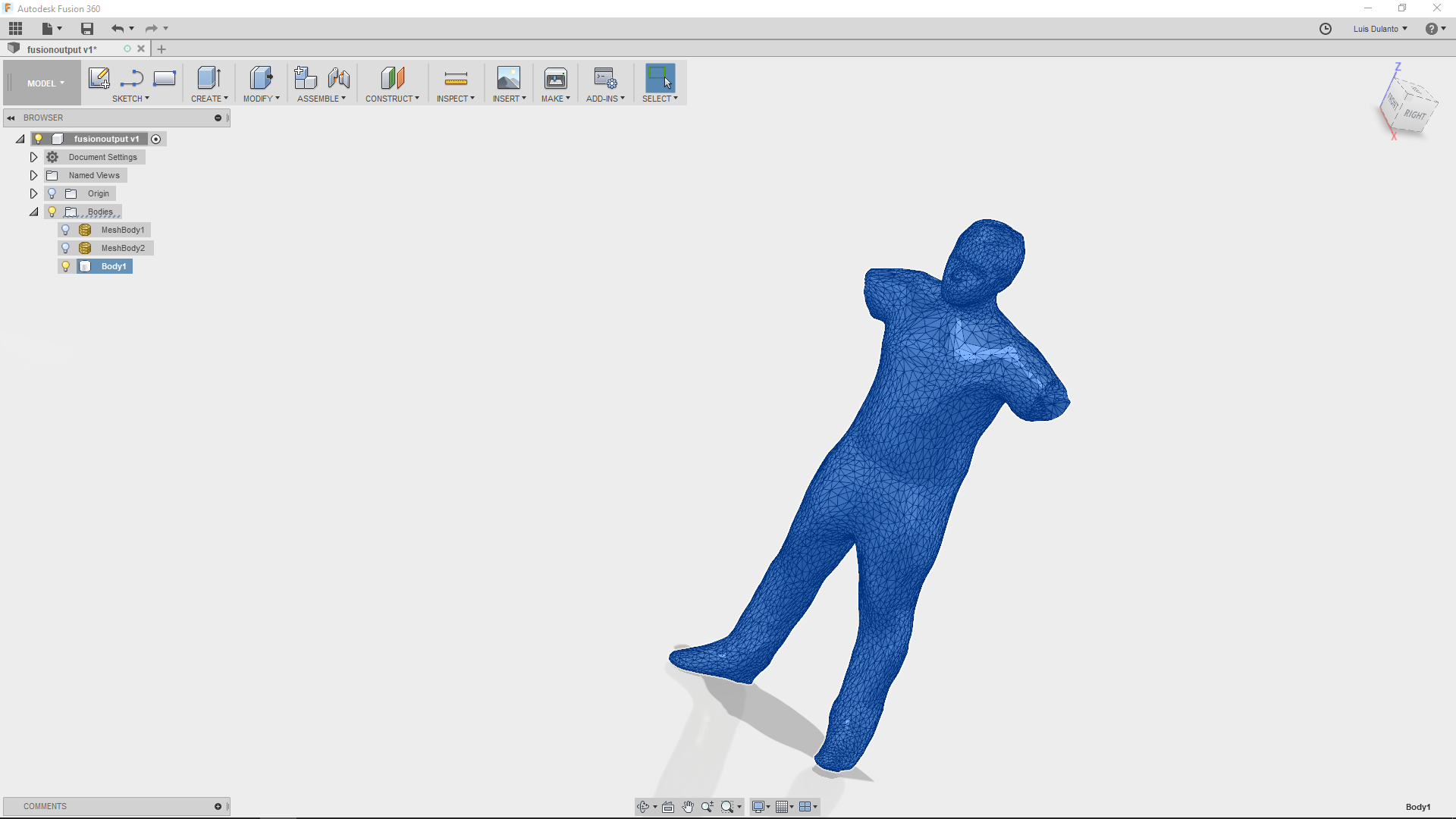
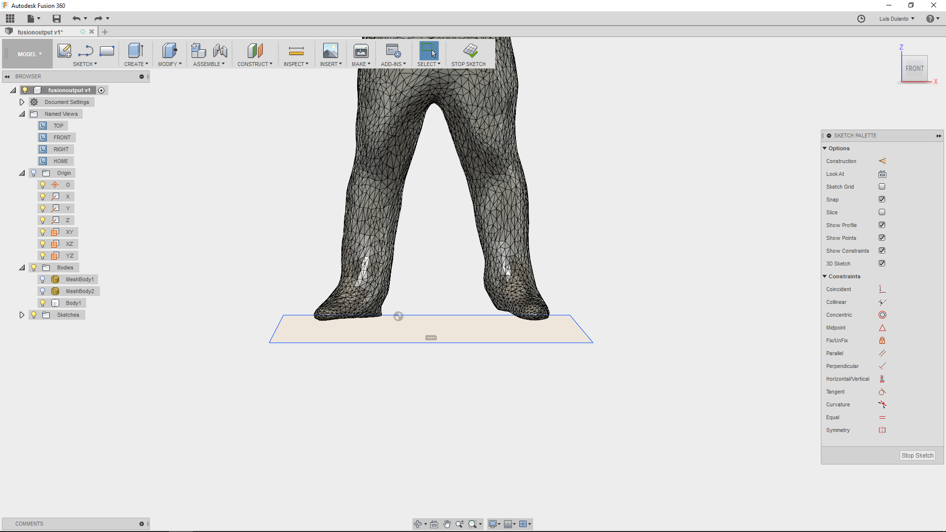
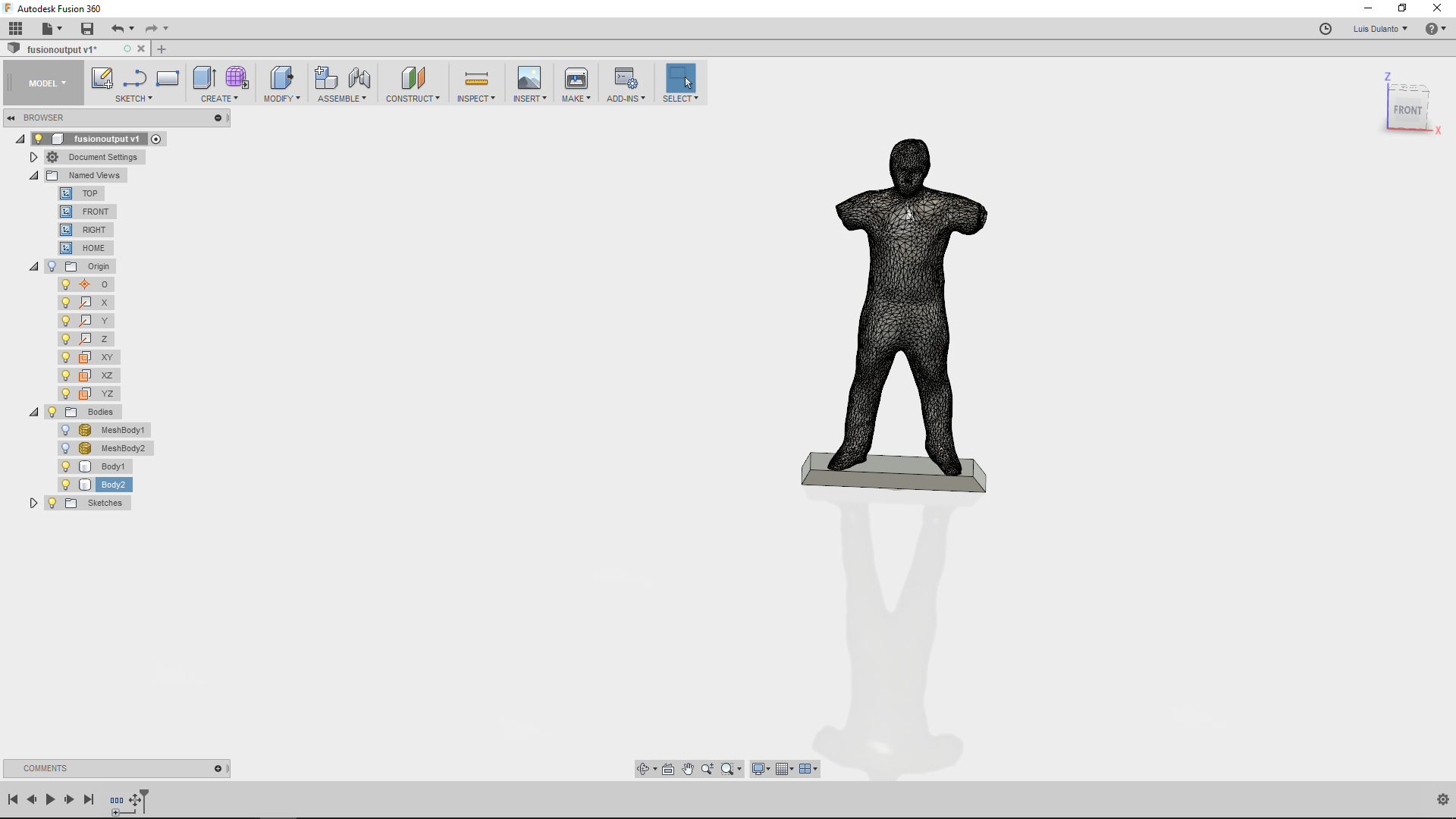
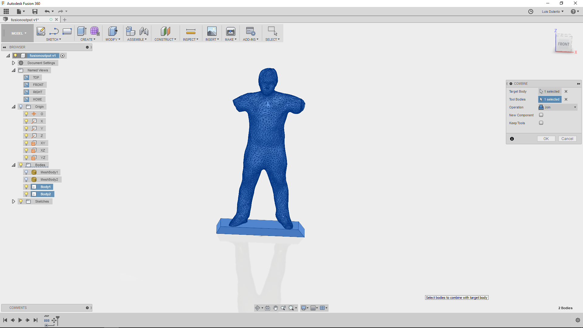
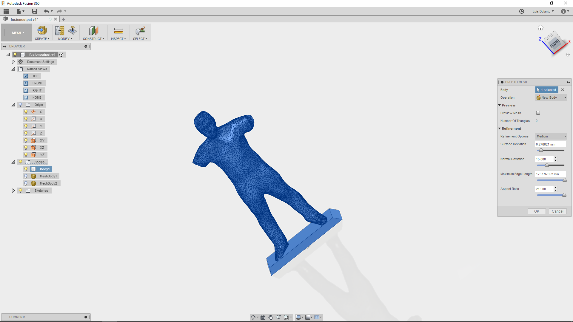
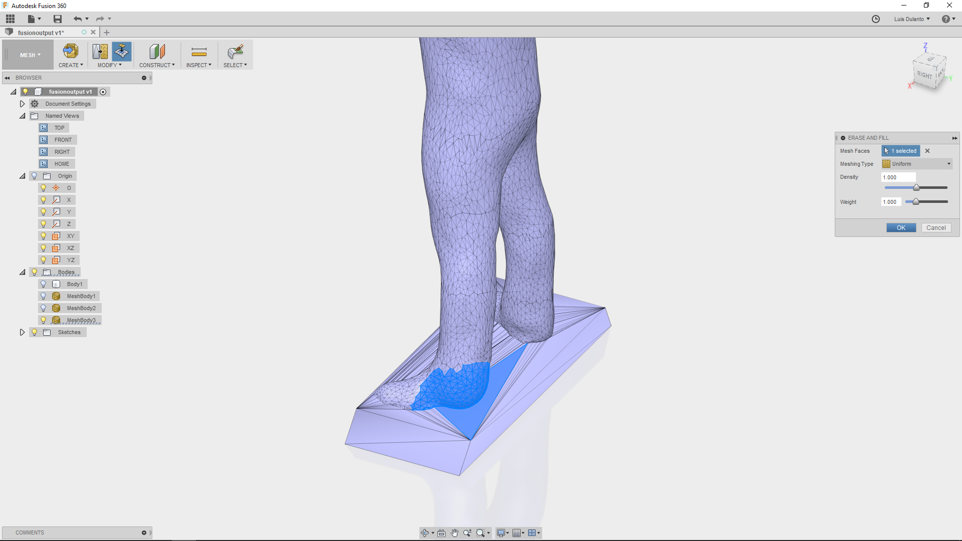
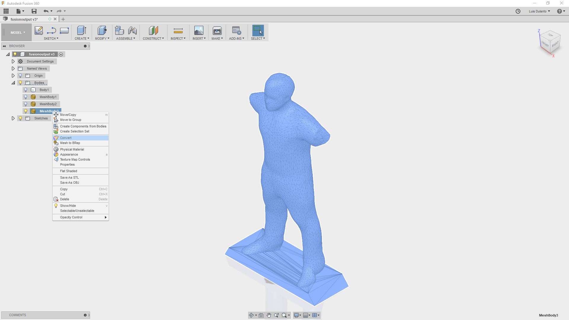
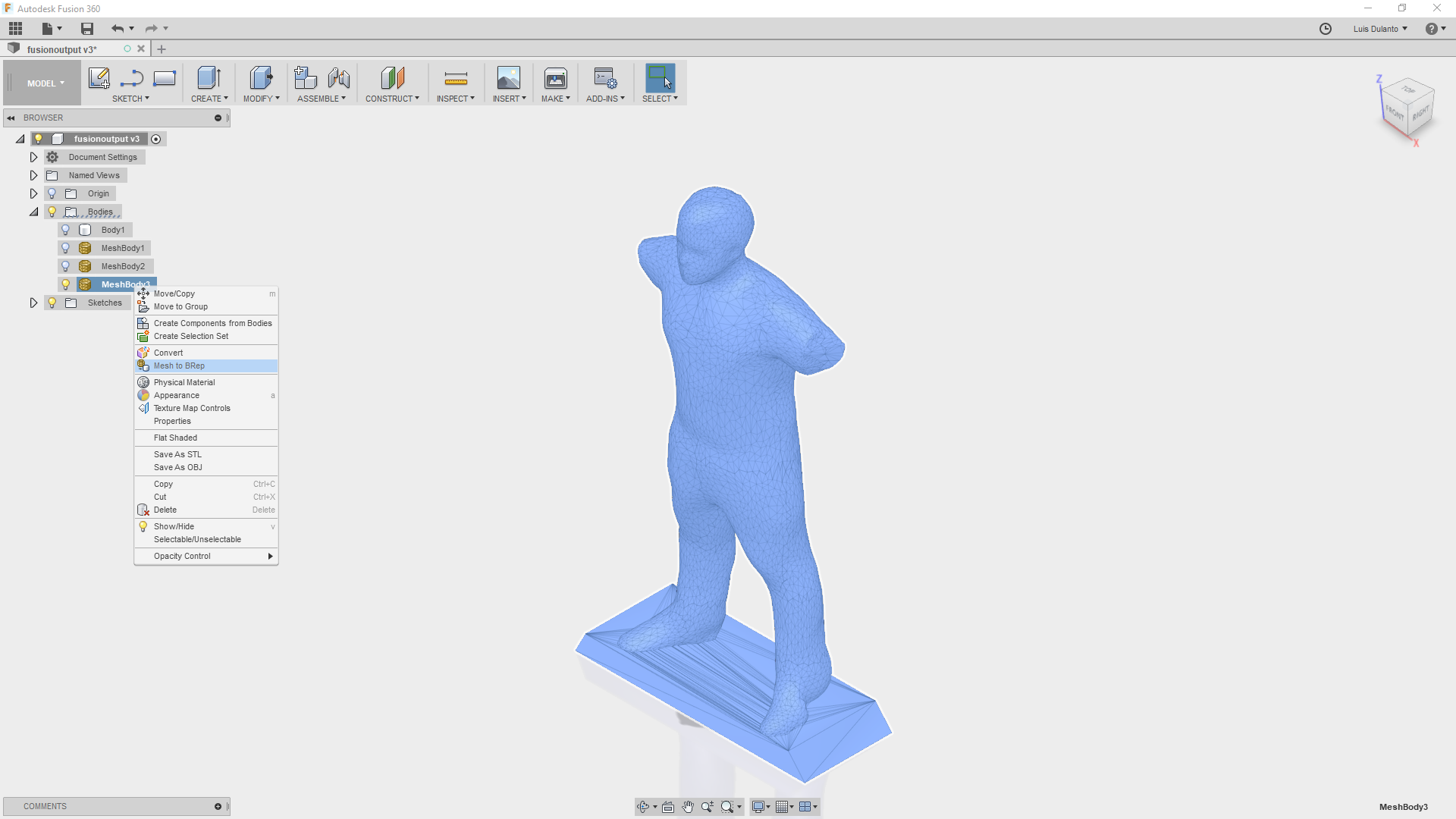
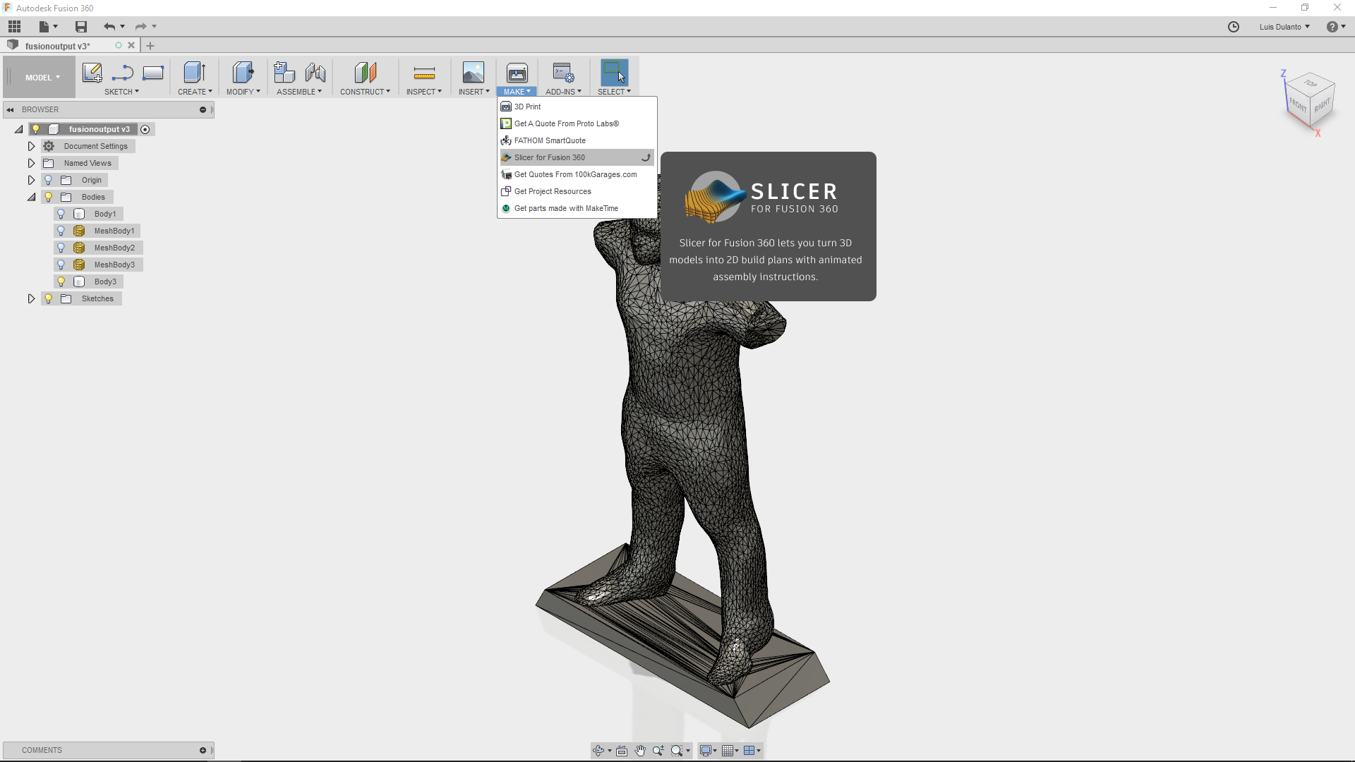
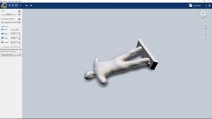
I wanted to add a pedestal to the body and eliminate the arms, so I loaded the stl file in Fusion 360 for editing the body. In general, I loaded the file and disabled the capture of history events, then I entered in Mesh mode and deleted the arms. Then I reduced the quantity of polygons in the mesh and converted the Mesh to a Body. After that, I went back to Model mode, created a pedestal in a sketch and extruded it close to the body with the join option selected. Then, I realized that the joining was not well done, so I converted the new joined body into a mesh and edited the unions. Finally, I converted the mesh into a body and exported the file as an STL. The process followed is shown on the images bellow.
Working With Slicer Plugin
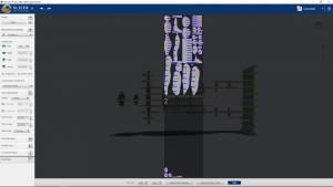
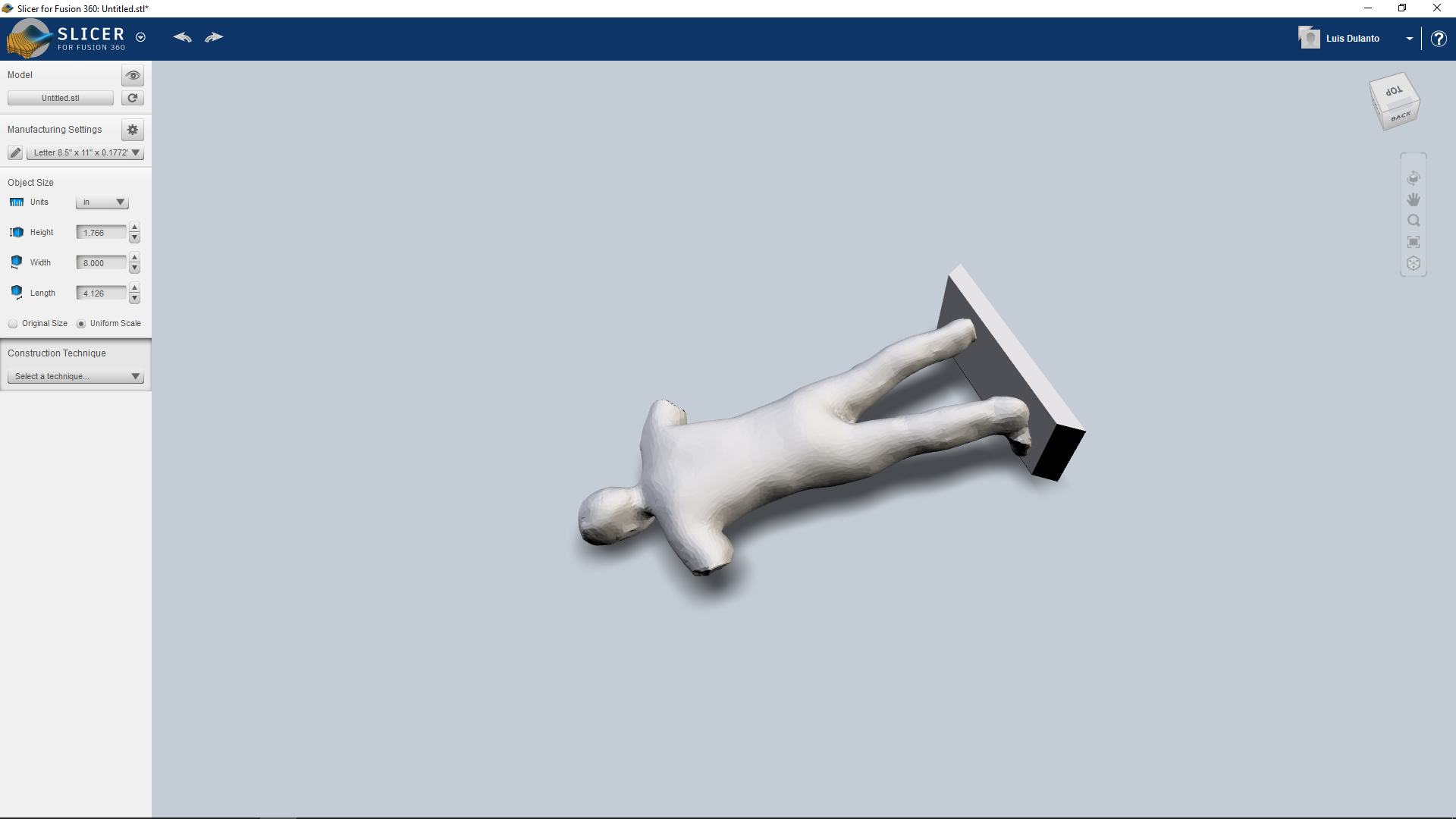
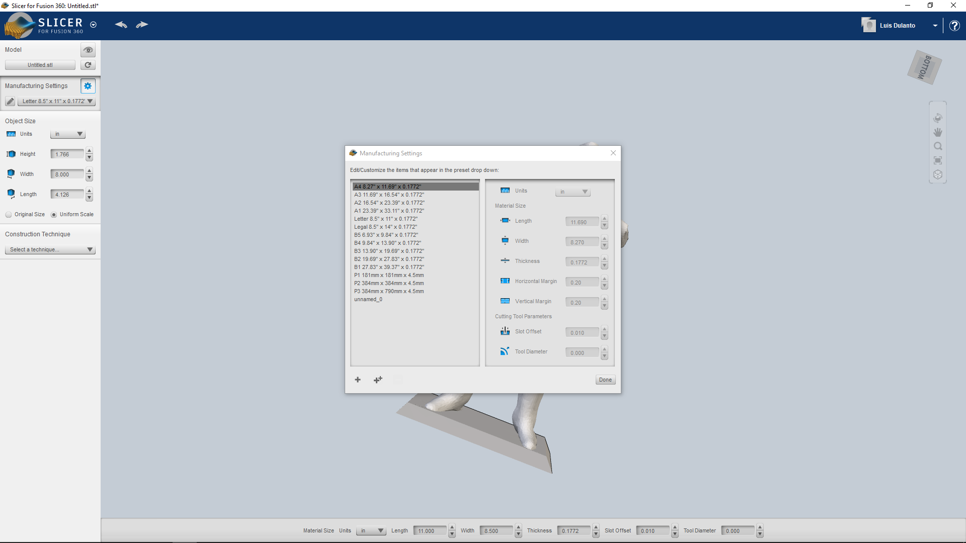
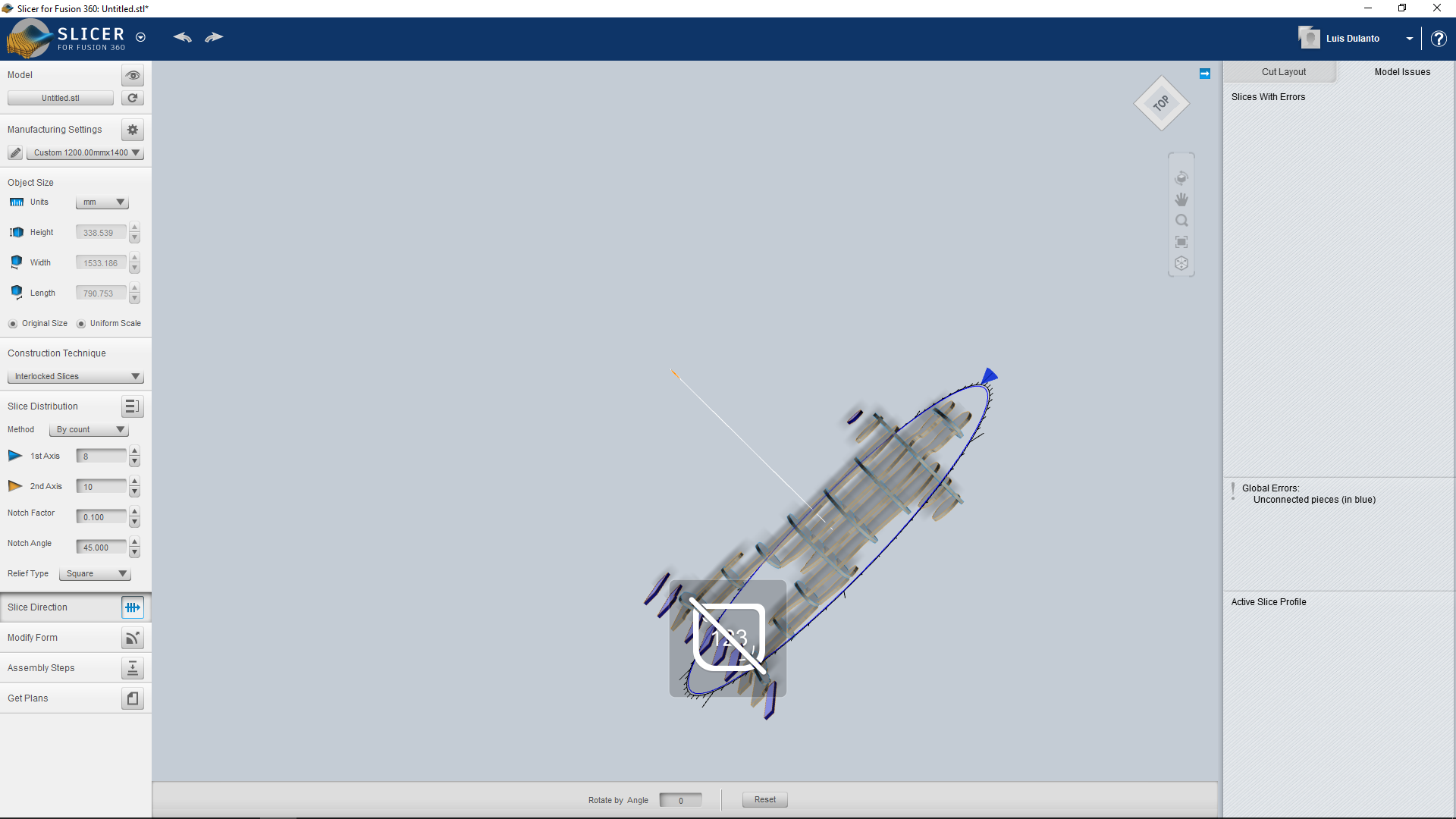
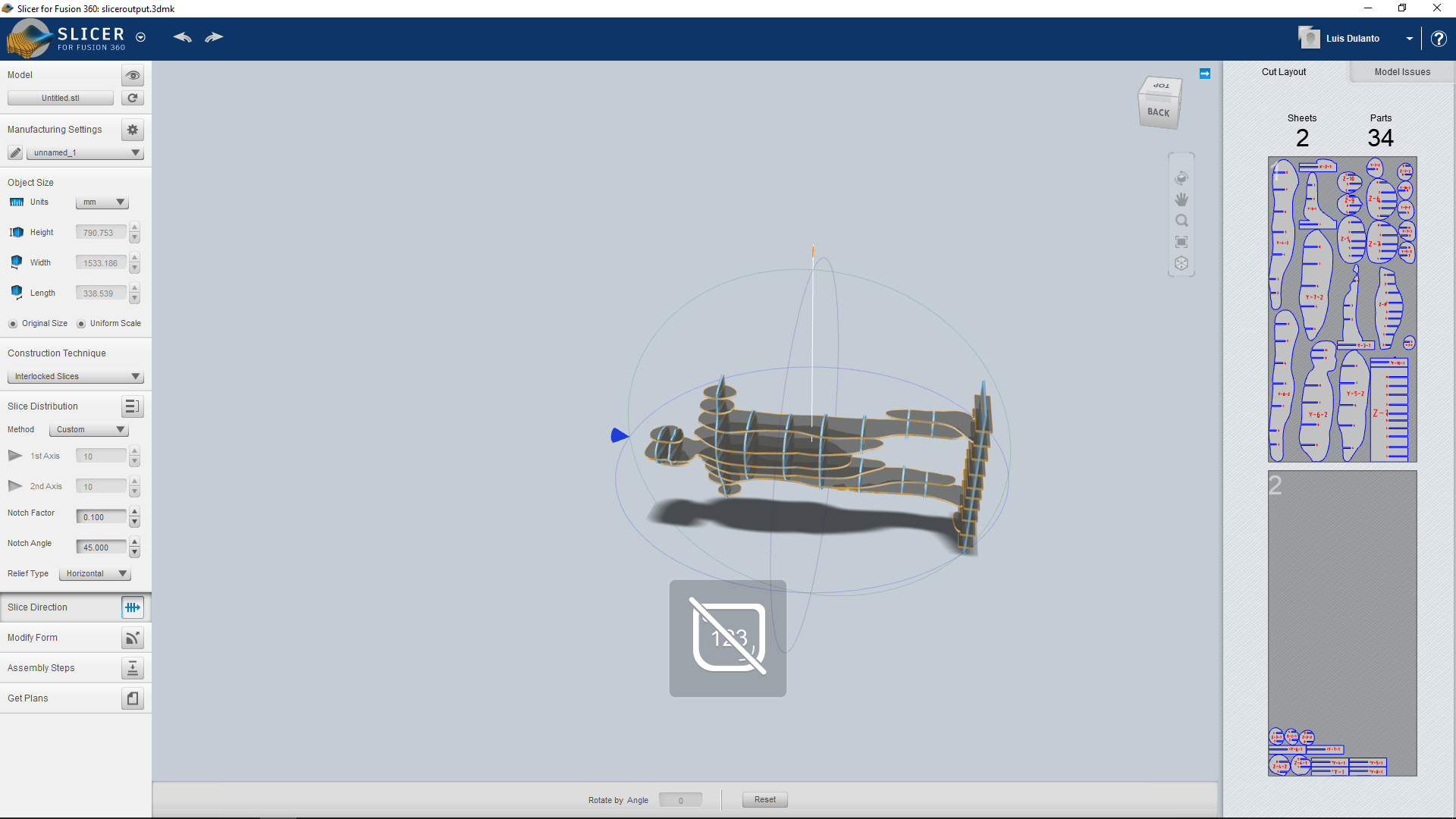
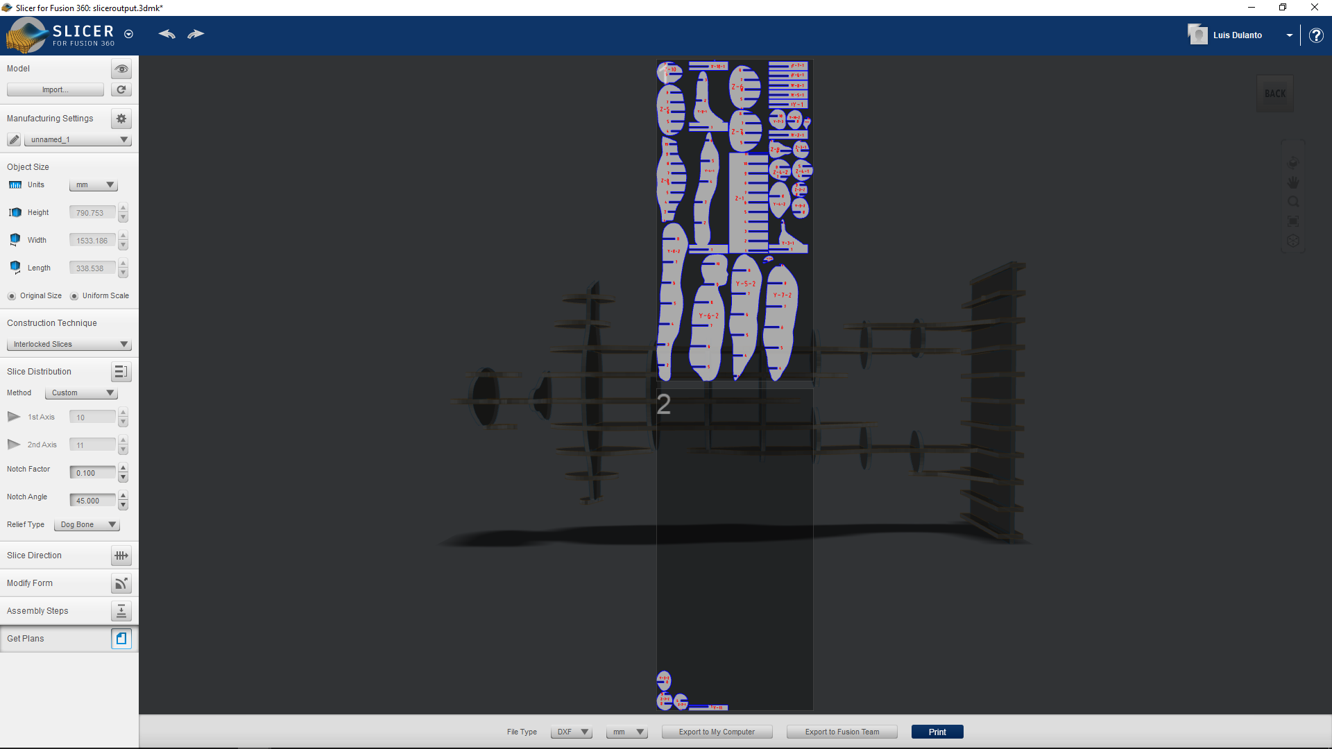
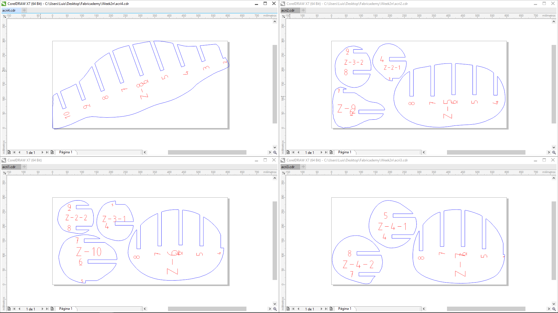
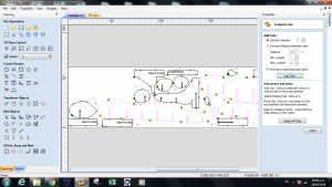
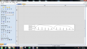
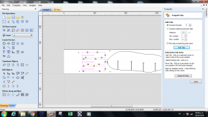
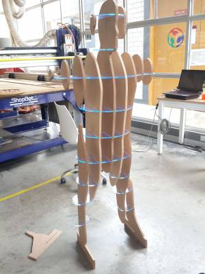
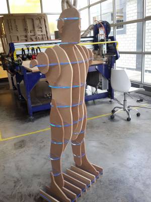
Since I needed to manufacture the body, I used the slicer plugin in fusion 360 for creating a waffel structure and getting the plans for milling or cutting it. What I did here was to import the file and create a new size for the plans. I created one of 1200 meters x 2400 meters, this was going to be the size of the MDF that I was going to use for milling the pieces. Then I selected Interlocked Slices and changed the direction of the pieces so that face of all the pieces were perpendicular to the front of the body. Finally, I clicked on get plans and exported the plans with two different thickness, one of a 12.1 mm for getting plans for a 6 mm acrylic board and one of 6.5 mm for an 12mm MDF, this measures were determined after testing.
Fabricating my own mannequin
Testing
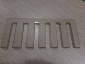
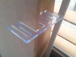
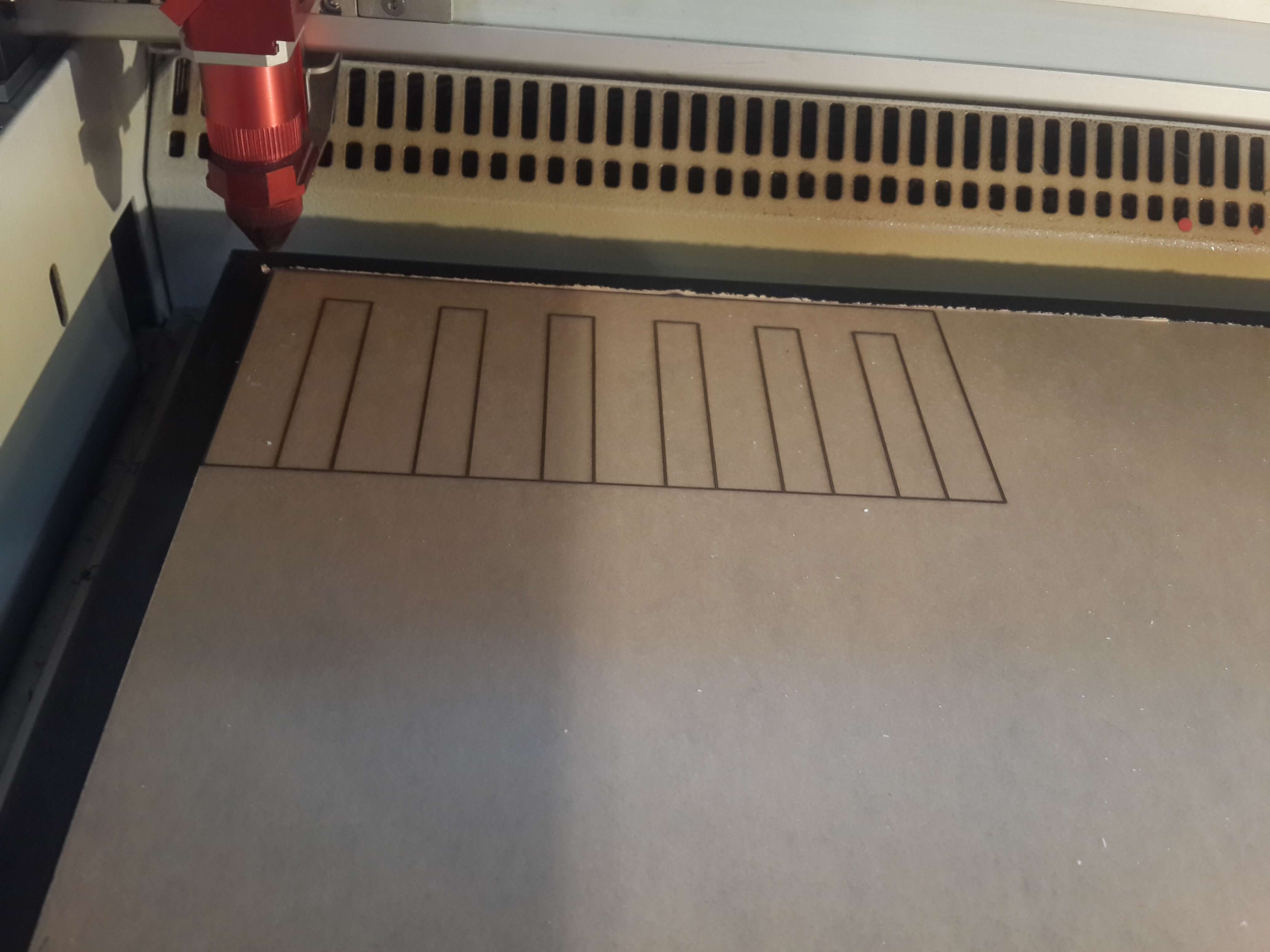
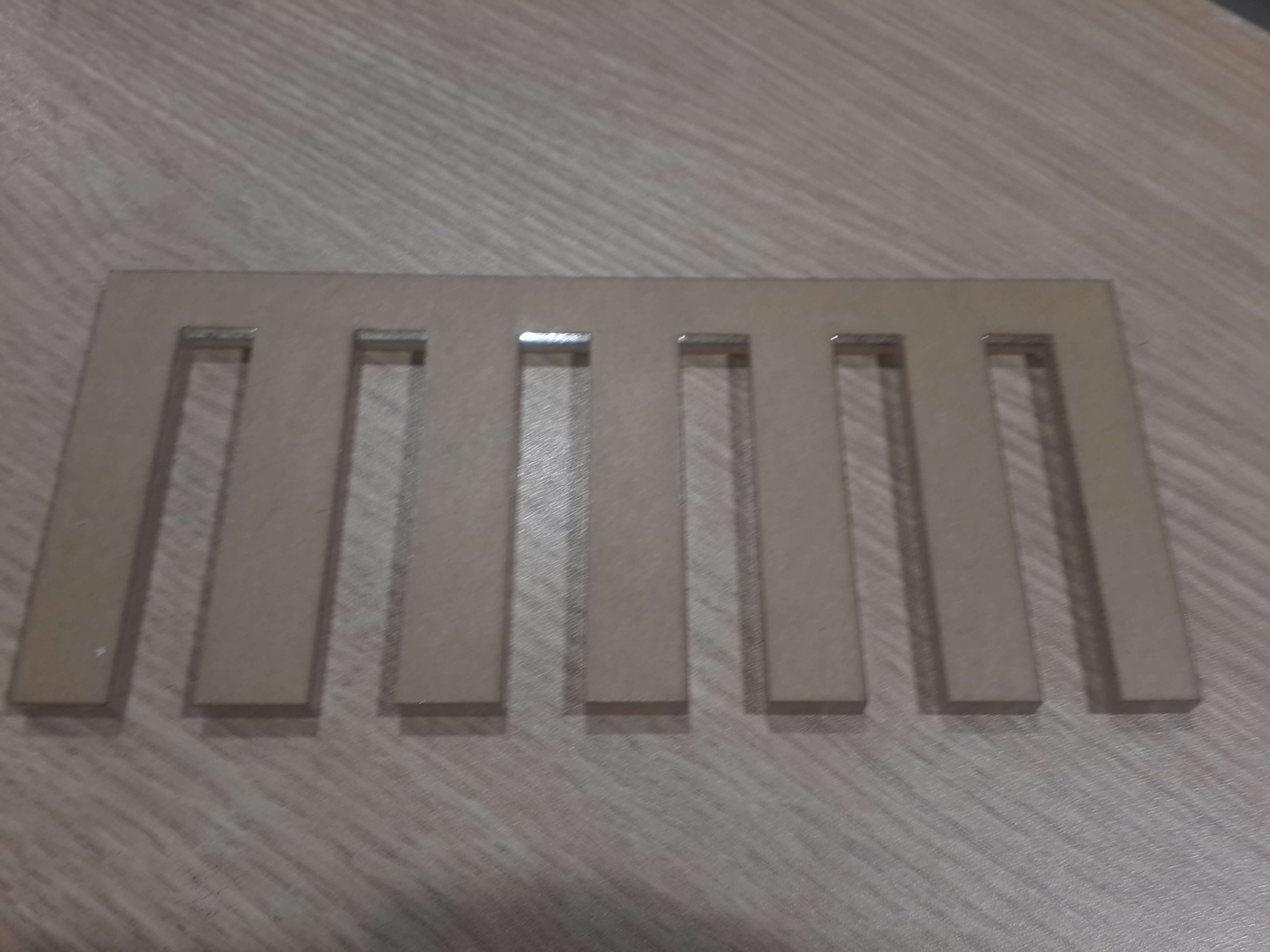
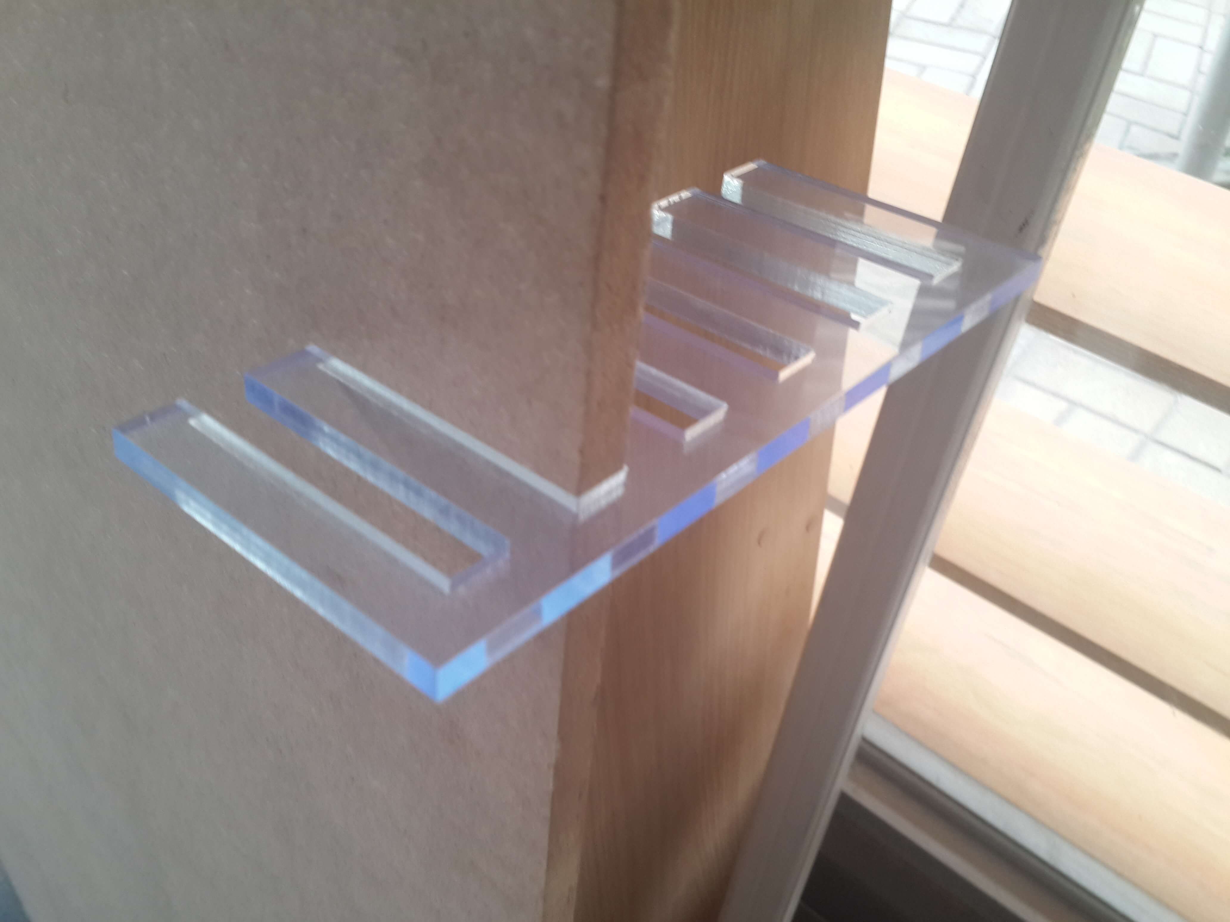
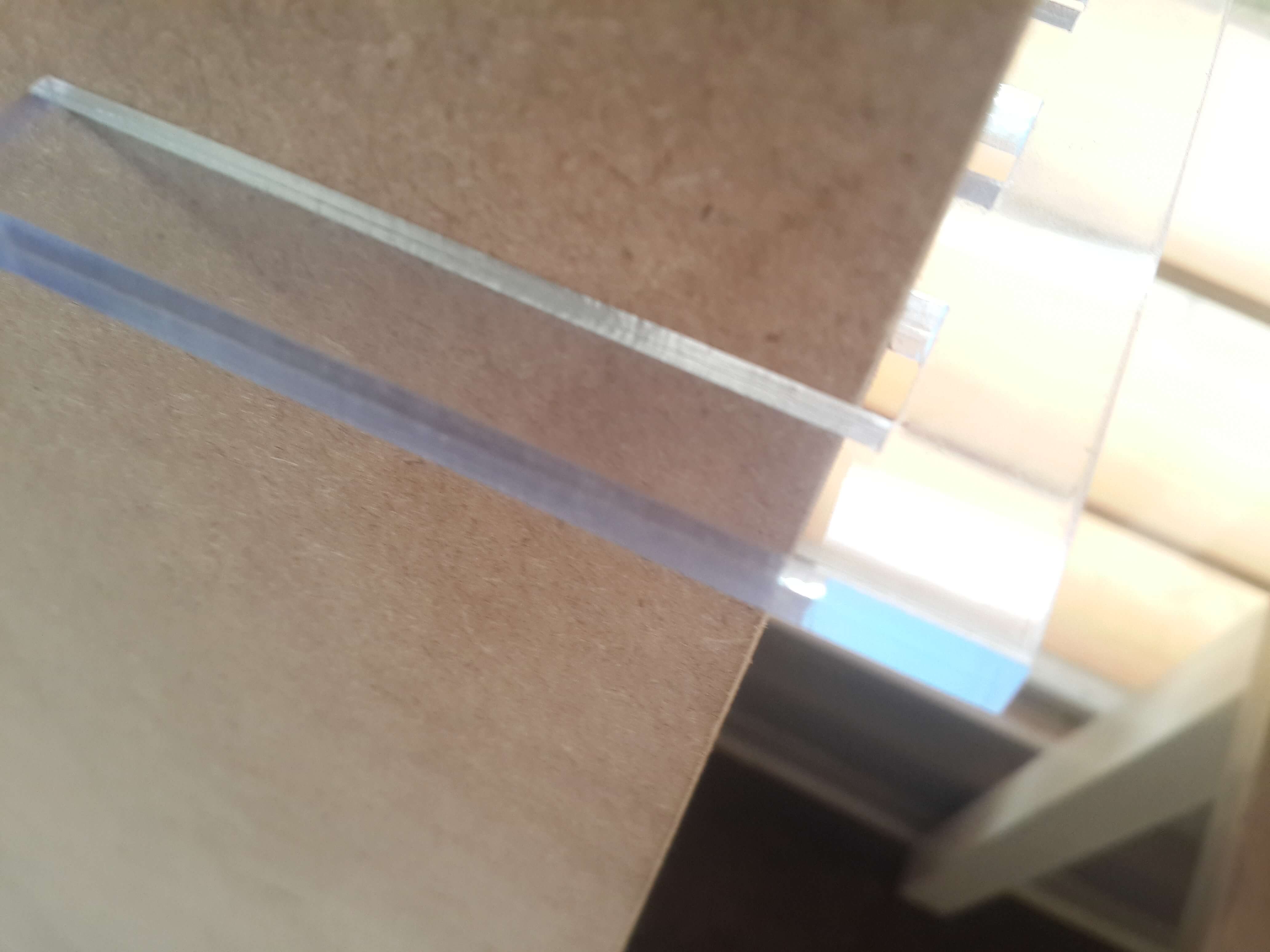
For finding the correct size of the holes on the Acrylic, I ceated a pattern with holes of different sizes in a range of 12 mm to 12.5 mm and tested it with a 12 mm MDF board. The result was that the holes need to be of 12.1mm for the acylic board.
Since the five 6 mm acrylic boards that I had to cut had variable thickness, I assigned 6.5 mm holes for the MDF board so that they will all fit in the MDF holes and wont broke because of overpressure on the unions.
So, I exported two times the plans with the slicer software. I selected the horizontal pieces of the plans of 12.1 mm, since this were the ones that were made of Acrylic so they had to join the 12 mm MDF, and selected the vertical pieces of 6.5 mm, since this are the ones made of MDF that need to join a 6 mm Acrylic.
Fabricating Horizontal Slices With the Laser Cutter
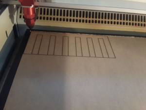
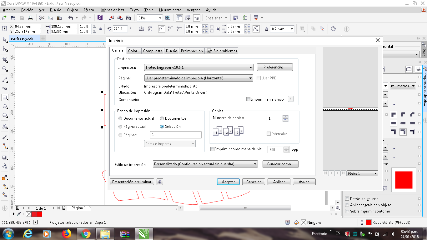
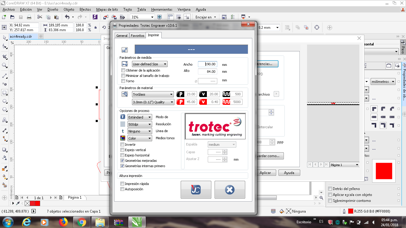
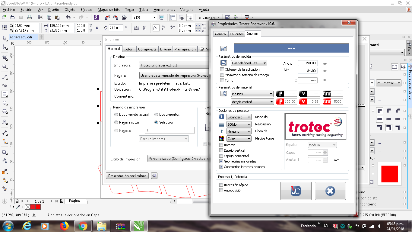
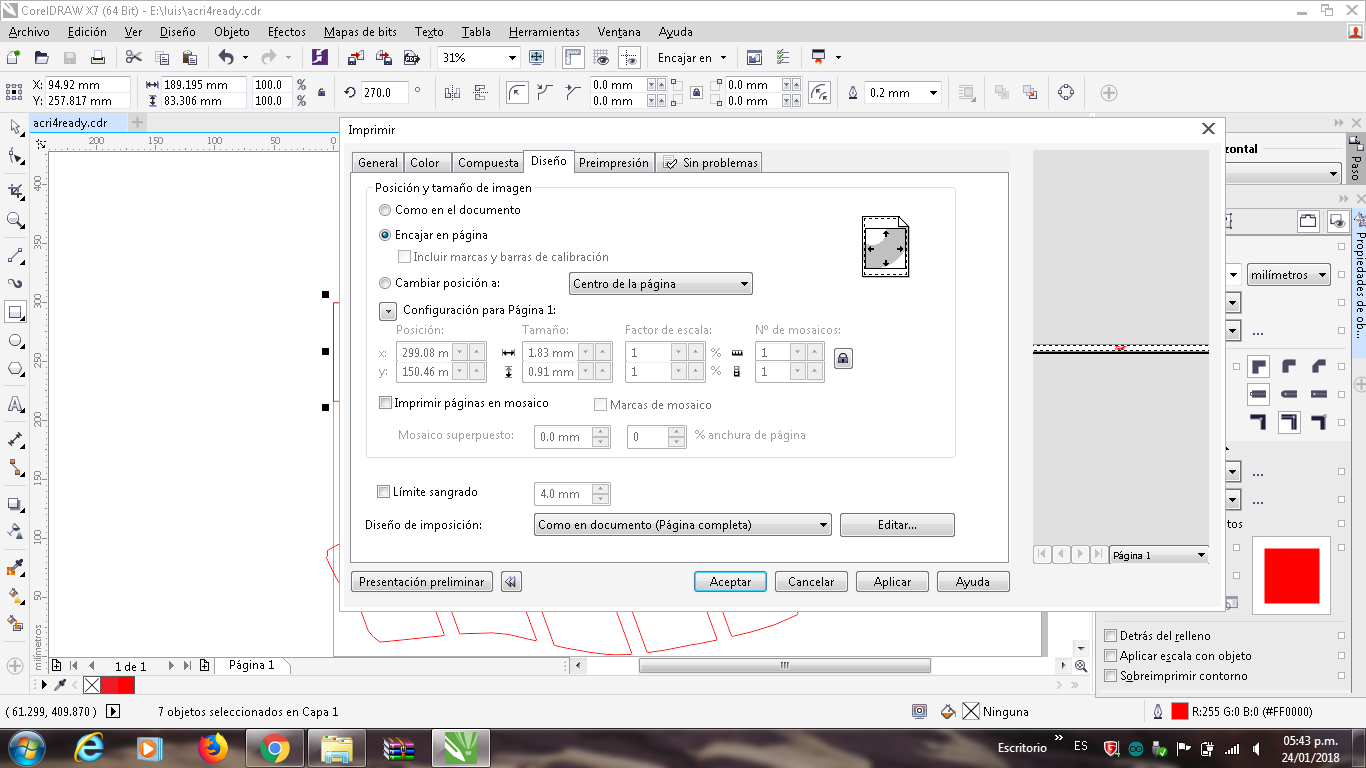
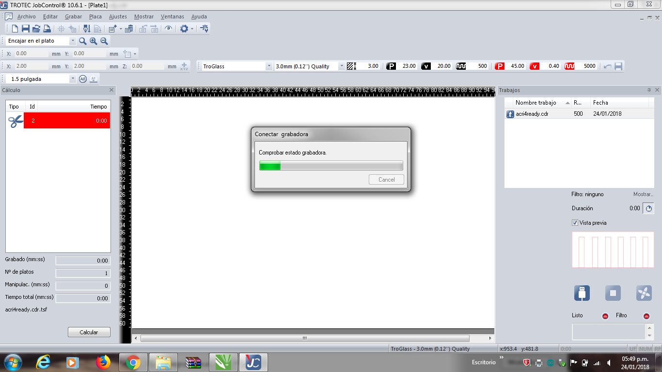
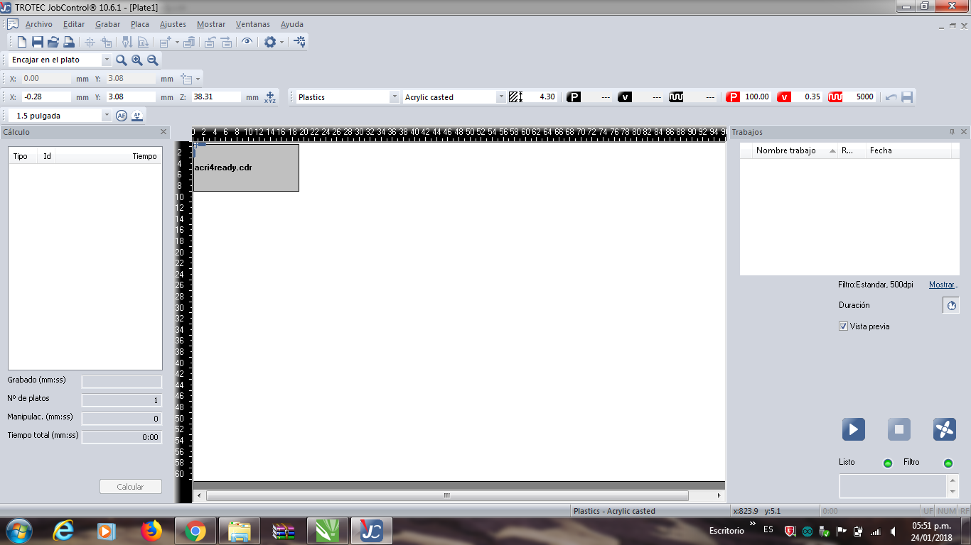
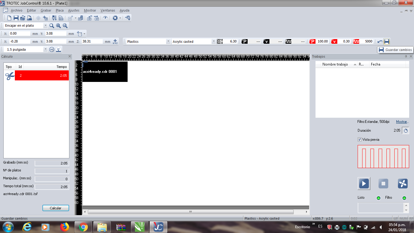
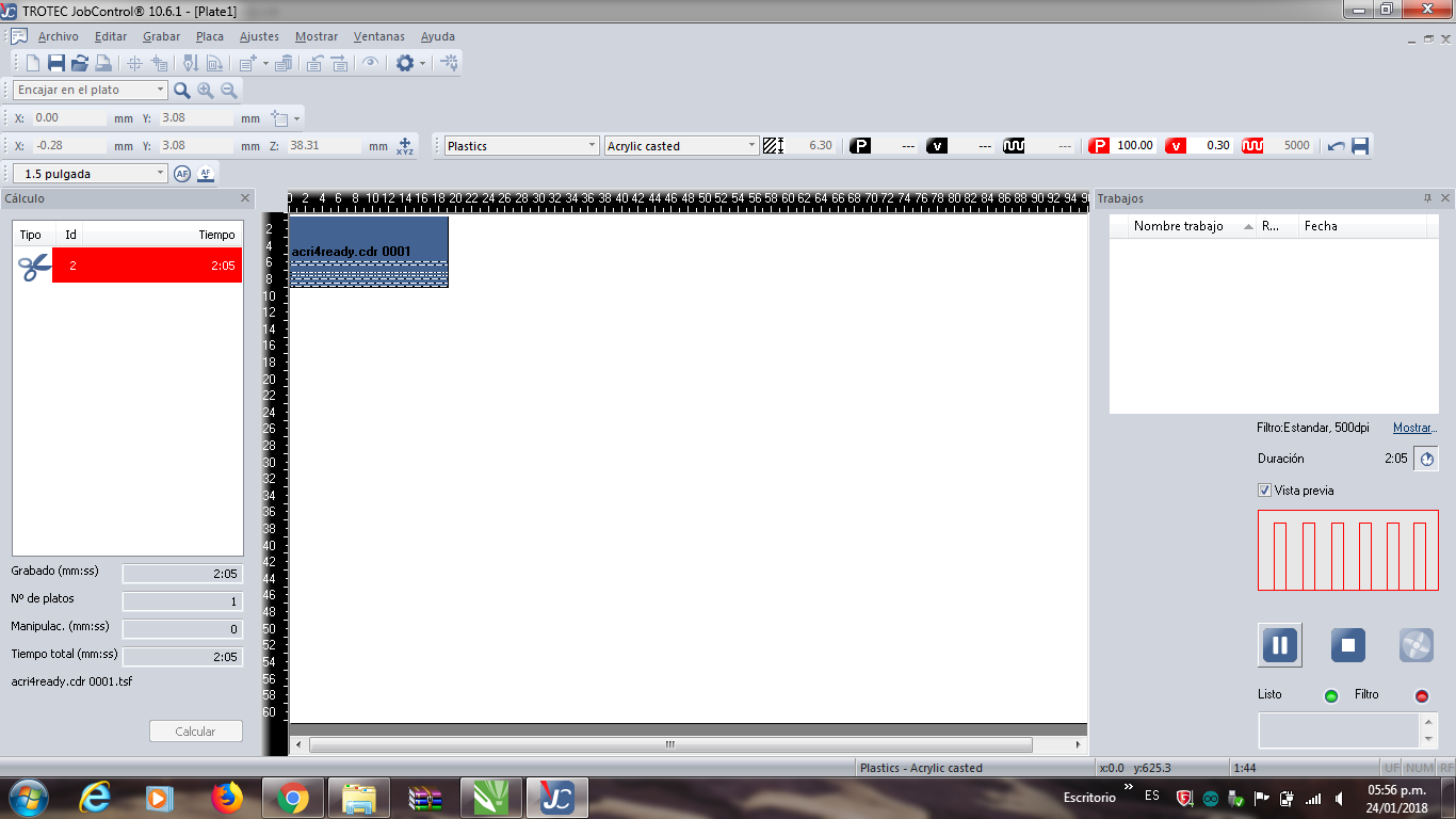
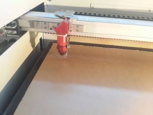
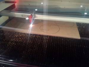
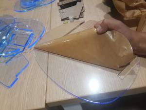
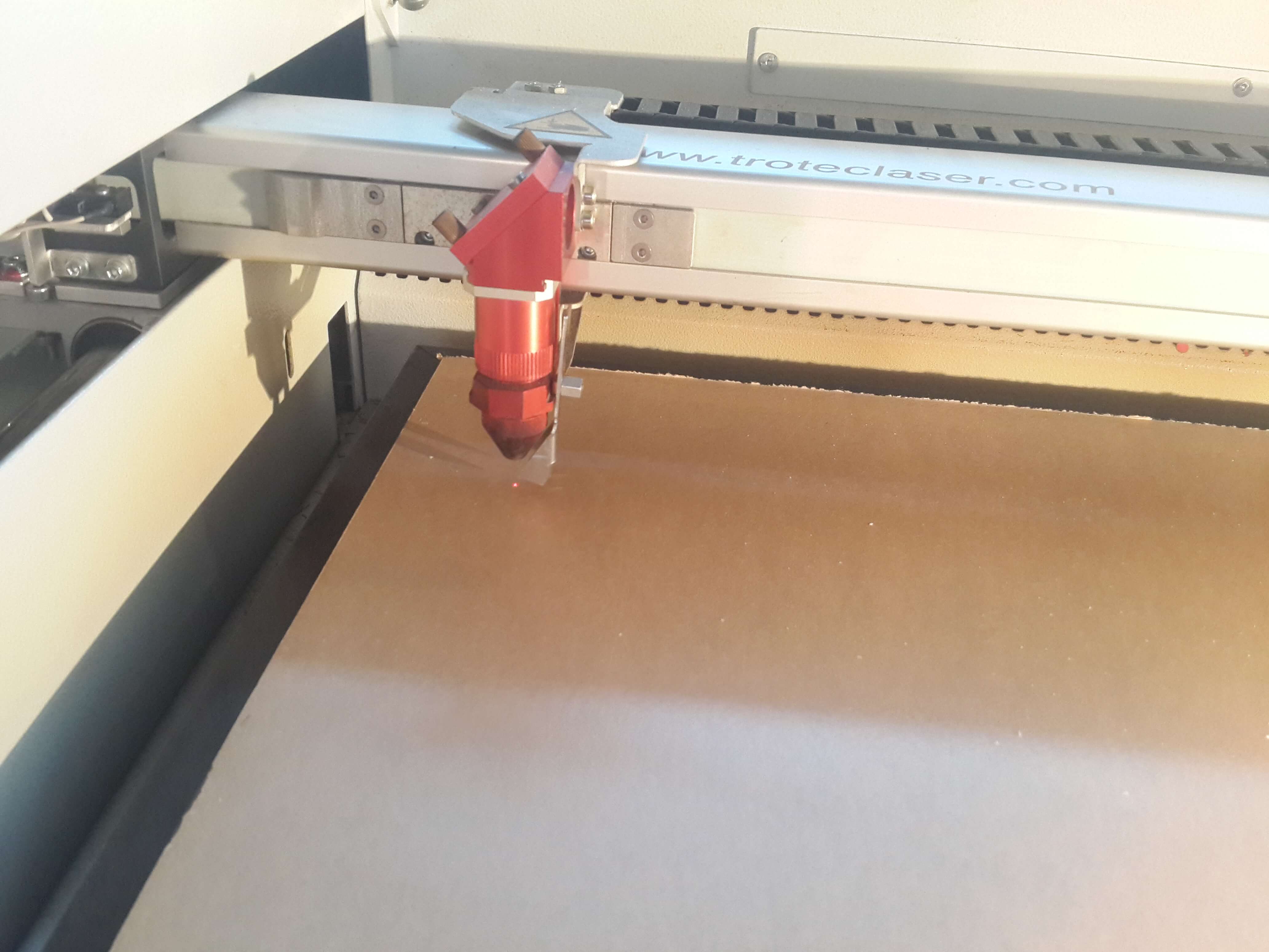
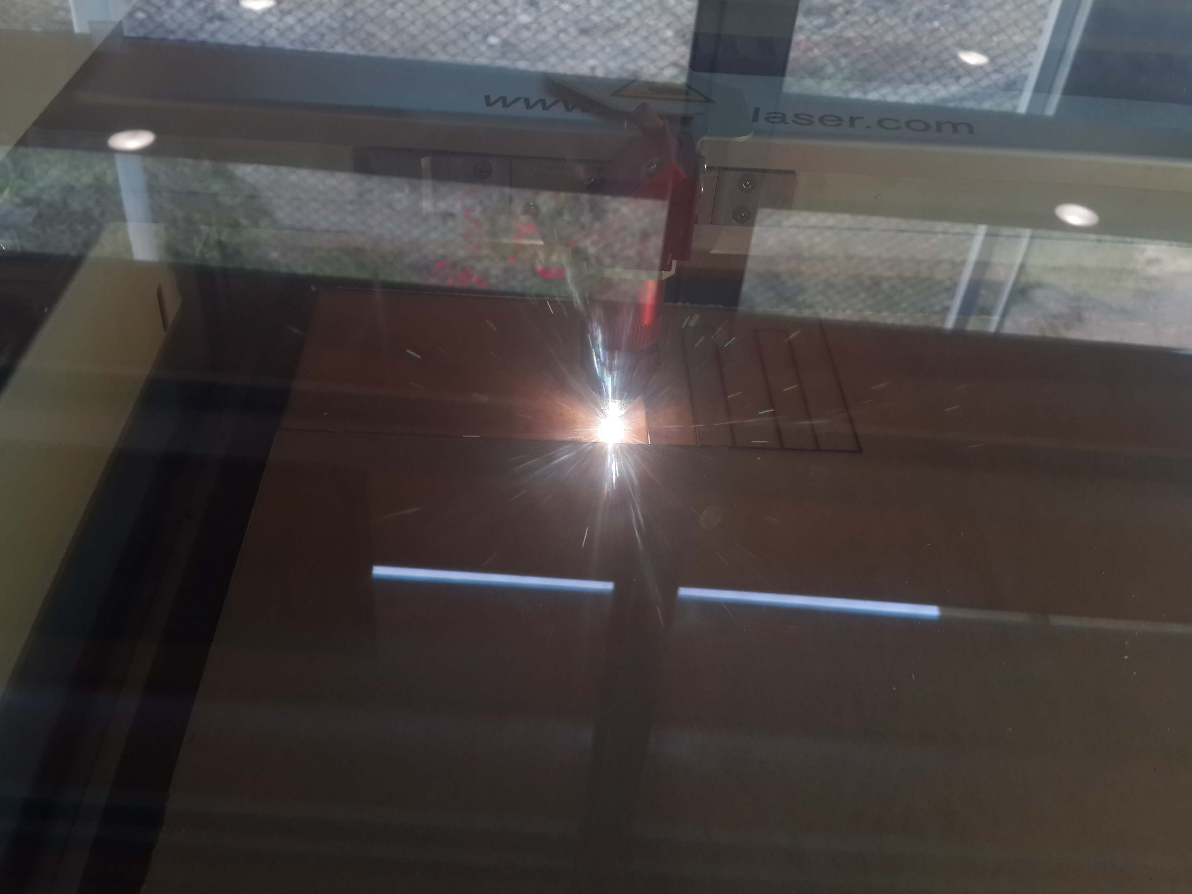
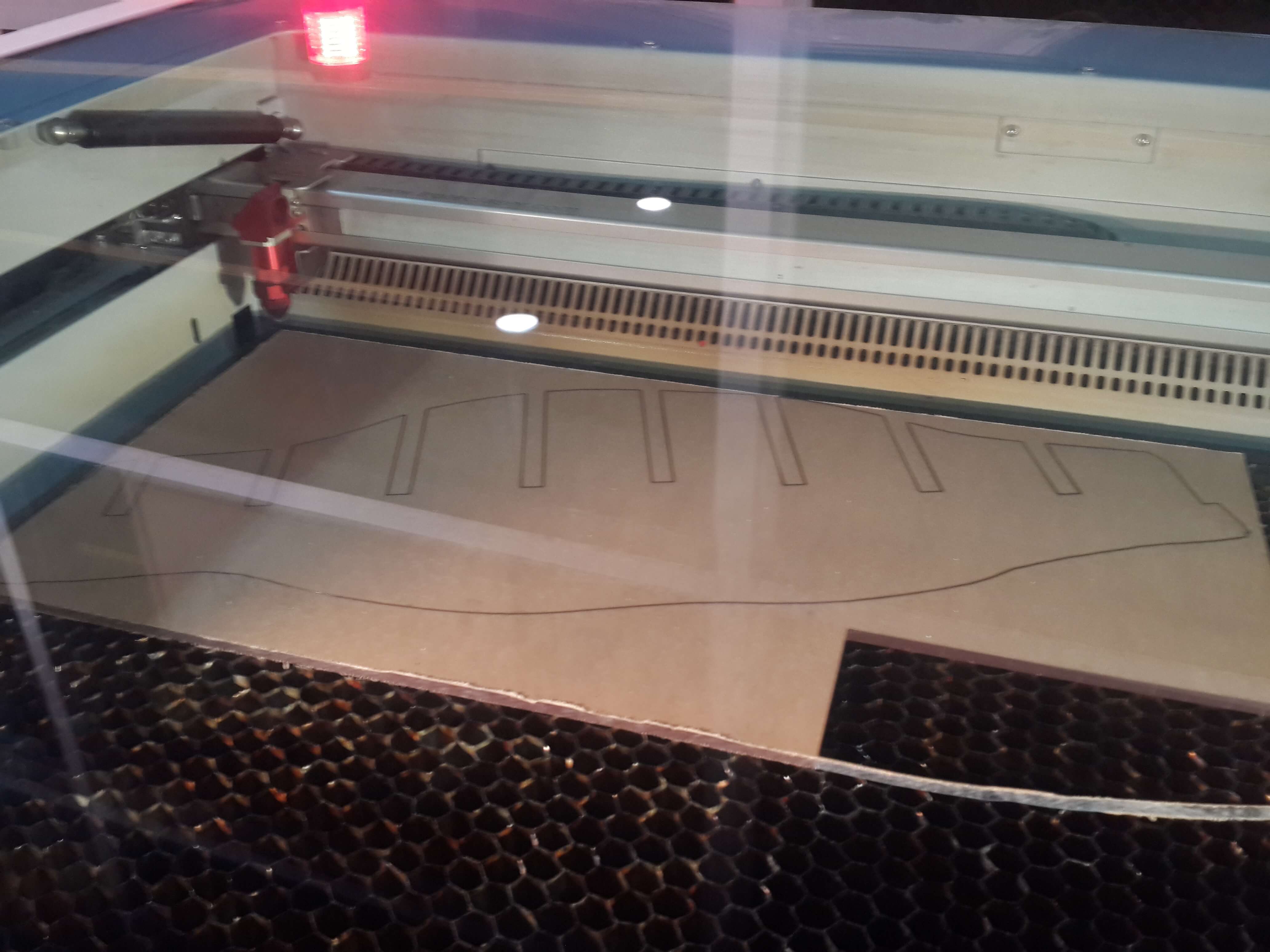
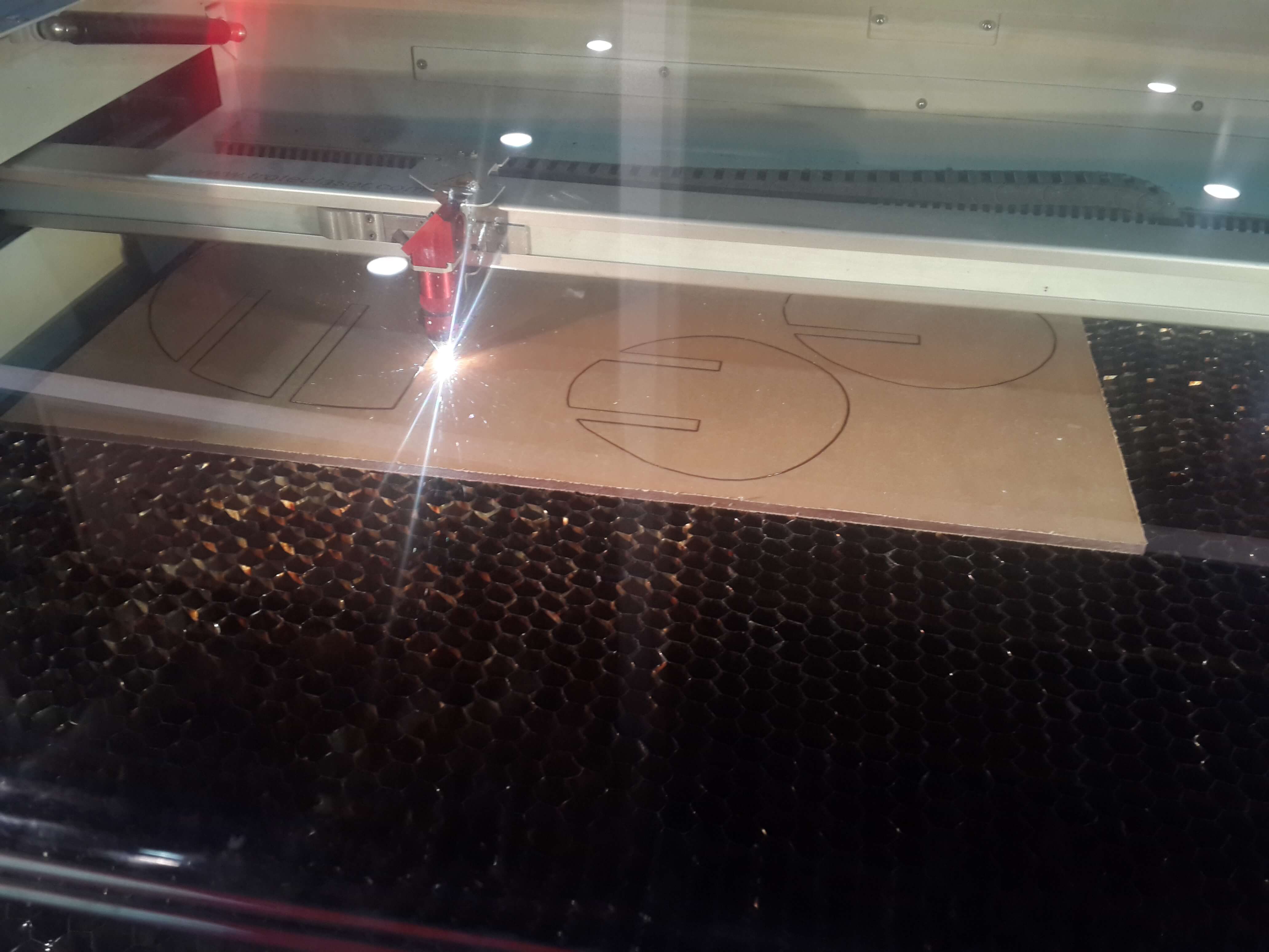
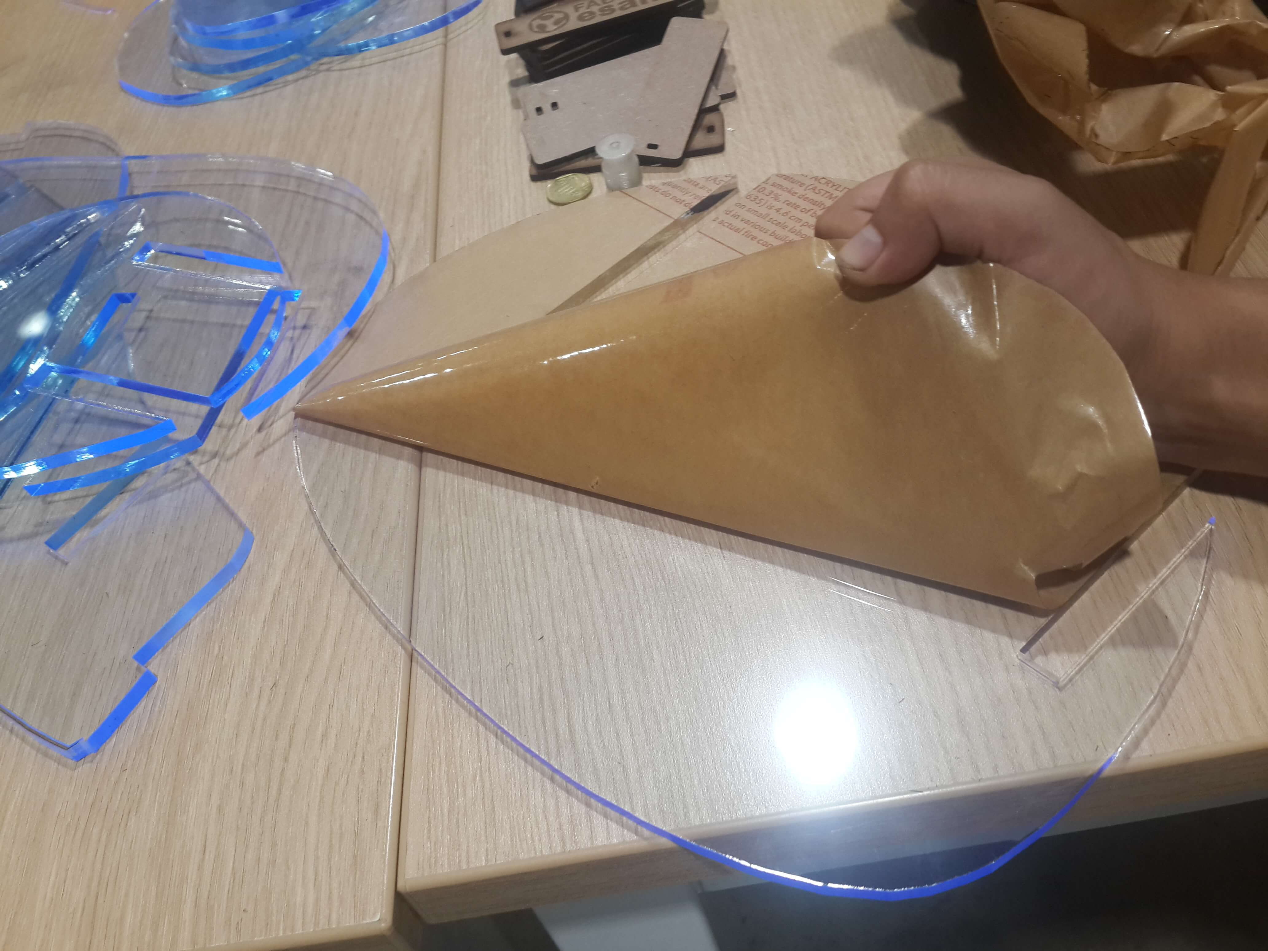
This are the ones made of acrylic. In general, I turned on the lasser cutter and calibrated the distance between the lazer and the acrylic board. Then I cutted a piece for testing and realized that the speed and power were not enought, so I just edited it on the top bar and saved and continued cutting the rest of the pieces. For cutting each piece I selected the pieces that I wanted to cut, clicked on print, selected the option print selection, then on the design tab selected the option “Change position” to “center of the page”, then on preferences I specified the dimensions of the selection and selected the material as Plastic and Acrylic Based. Finally I sent it to print and on the Trotec Software I dragged the printing file to the place of the board were I wanted to be cutted the pieces.
Fabricating Vertical Slices With the ShopBot
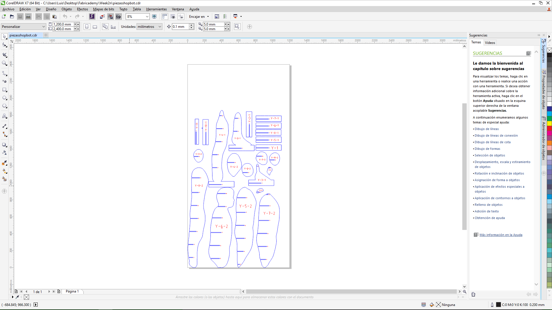
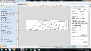
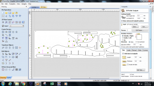
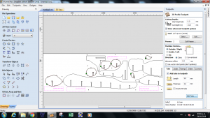
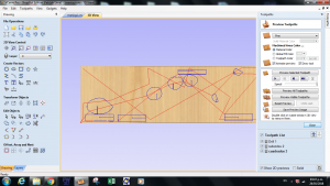
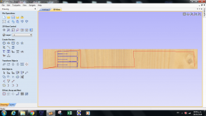
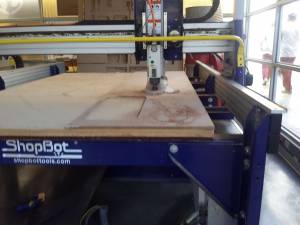
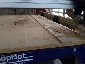
This are the ones made of MDF. In this case I neede to edit my plans in the Vcarve software. So In genereal, I loaded the file in the vcarve software and sincce there were no MDF board of 12mm with the size of my plans I had to move the pieces so that they fit in the MDF board available; once I did that, I checked if there were no unconected lines in my plans; then I created T bone ears in each inner corner; after that I created circles around my pieces, this are the places for the screws; then I selected on the toolpath the drill option, asignned a depth of 3mm, gave it a name to the toolpath and calculated it; then I selected the smaller pieces changed the thickness of milling to 13 mm (one mm extra to the thickness of my board), then iselected the cutting path as outside and added tabs of 3mmX5mm to each piece. Then I repeated the same process for the reste of the pieces. Fianlly, I saved each individual toolpath.
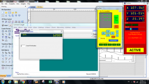
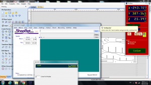
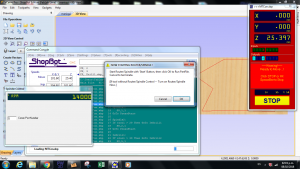
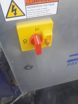
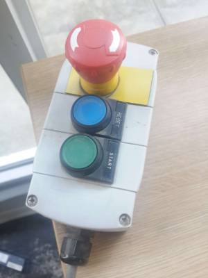
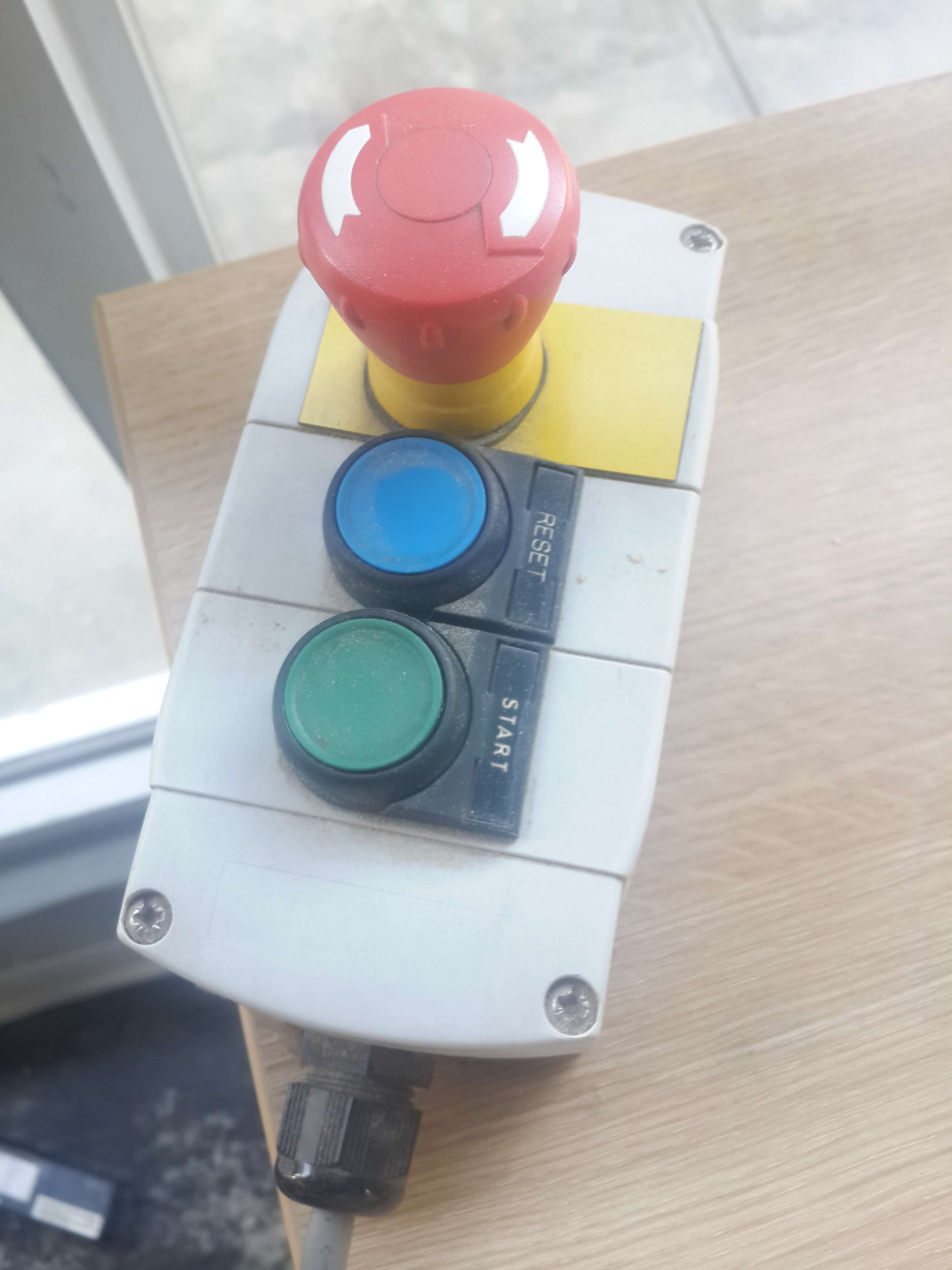
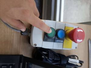
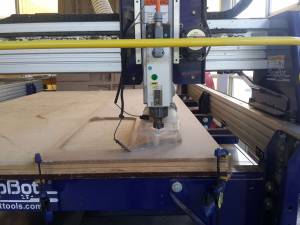
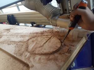
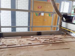
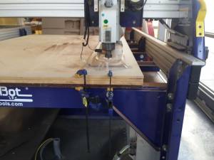
For milling the pieces, I turned on the shopbot milling machine and the spinning tool, and fixed the MDF board to the machine witg some holders; After that, I clicked on reset on the techpendant and calibrated the machine at Z direction, this was done with a conductive plate and and scissors, and calibrated it in the XY plane, this was done atumatically by clicking on the calibrate XY button; then, I loaded the drilling toolpath on the shopbot software, for making the holes where I was going to put the screws that fixed the MDF board to the machine; I clicked on the start button and then clicked on start on the techpendant, once I did this the machine started to make the holes. So I used dose holes for fixing the board with screws and then I loaded the tootlpath of the smaller pieces to be milled and hitted on start at the software and once again I clicked start with the techpendant and repetated those steps until all the pieces where milled.
Building my own mannequin
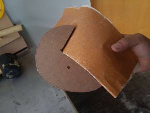
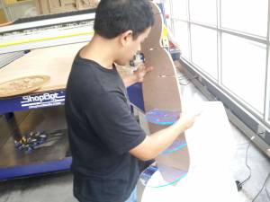
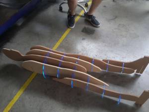
For building my mannequin, I had to sand all the pieces and then with the aid of Alexandra, Carlos and my tutor I built the mannequin.

