This is an old revision of the document!
Shirt Pac-Man
This shirt carries 14 LEDs sewn into Charlieplexing to occupy less outputs and thus improve the project in the future.

How create the circuit:
As seen in the diagram, pin Nº2 (Blue) connects with the positive of led 1 (green) and pin Nº3 with the negative of led 1. So, LED 1 will turn on. Since the current cannot flow through LEDs in reverse bias, the LED2 will stay off. If charges at the poles 2 and 3 are reversed, the LED 2 lights and LED 1 will turn off.

For 6 leds, it would be like that:

For this circuit to work as the previous one, we must disconnect one of the pins before applying the load to the remaining two. This can be solved by using the logical properties, the three states of pins. The pins usually have three states, HIGH, LOW and INPUT.
The input mode puts the pin into a high impedance state, electrically speaking, “off”, i.e., little or no current will flow through it. This allows the circuit select any number of pins connected at any time, simply changing the state of the pin.
In order to control the matrix of 6 LEDs shown, the two pins for the LED that we want activate must be connected to HIGH and LOW respectively, while the third pin is in its INPUT state. Doing it like that, prevents leakage of current off the third pin, ensuring that the LED you want to light is the only illuminated.
Circuit:

I used tape to prevent some wires touch.


Code:
int velocidad =500;
const int LED_1 = 2;     //LED row 1   Definimos donde esta pinchado la primera linea de charlieplexing
const int LED_2 =3;     //LED row 2    Definimos donde esta pinchado la segunda linea de charlieplexing
const int LED_3 =4;     //LED row 3    Definimos donde esta pinchado la tercera linea de charlieplexing
const int LED_4 = 5;     //LED row 1   Definimos donde esta pinchado la primera linea de charlieplexing
const int LED_7 = 6;

void setup()
{

  delay (velocidad);

}

void loop(){

  //turn on LED L1
  pinMode (LED_1, OUTPUT);     //row 1 lo pone a OUTPUT y lo establece a 0
  digitalWrite (LED_1,HIGH);
  pinMode (LED_2, OUTPUT);     //row 2 lo pone a OUTPUT y lo establece a 1
  digitalWrite (LED_2, LOW);
  pinMode (LED_3, INPUT);   //row 3 lo pone a INPUT y lo establece a 0
  digitalWrite (LED_3, LOW);
   pinMode (LED_4, INPUT);      //row 3 lo pone a INPUT y lo establece a 0
  digitalWrite (LED_4, LOW);
   pinMode (LED_7, INPUT);      //row 3 lo pone a INPUT y lo establece a 0
  digitalWrite (LED_7, LOW);

  delay (velocidad);

  //turn on LED L2
  pinMode (LED_1, OUTPUT);
  digitalWrite (LED_1,LOW);
  pinMode (LED_2, OUTPUT);
  digitalWrite (LED_2,HIGH);
  pinMode (LED_3, INPUT);
  digitalWrite (LED_3, LOW);
  pinMode (LED_4, INPUT);
  digitalWrite (LED_4, LOW);
  pinMode (LED_7, INPUT);
  digitalWrite (LED_7, LOW);

  delay (velocidad);

  //turn on LED L3
  pinMode (LED_1, INPUT);
  digitalWrite (LED_1, LOW);
  pinMode (LED_2, OUTPUT);
  digitalWrite (LED_2, HIGH);
  pinMode (LED_3,OUTPUT);
  digitalWrite (LED_3,LOW);
  pinMode (LED_4, INPUT);
  digitalWrite (LED_4, LOW);
  pinMode (LED_7, INPUT);
  digitalWrite (LED_7, LOW);

  delay (velocidad);

  //turn on LED L4
  pinMode (LED_1, INPUT);
  digitalWrite (LED_1, LOW);
  pinMode(LED_2, OUTPUT);
  digitalWrite (LED_2,LOW);
  pinMode (LED_3, OUTPUT);
  digitalWrite (LED_3, HIGH);
    pinMode (LED_4, INPUT);
  digitalWrite (LED_4,LOW);
  pinMode (LED_7, INPUT);
  digitalWrite (LED_7, LOW);

  delay (velocidad);

  //turn on LED L5
  pinMode (LED_1, INPUT);
  digitalWrite (LED_1, LOW);
  pinMode (LED_2, INPUT);
  digitalWrite (LED_2, LOW);
  pinMode (LED_3, OUTPUT);
  digitalWrite (LED_3, HIGH);
   pinMode (LED_4,OUTPUT);
  digitalWrite (LED_4, LOW);
  pinMode (LED_7, INPUT);
  digitalWrite (LED_7, LOW);

  delay (velocidad);

  //turn on LED L6
  pinMode (LED_1, INPUT);
  digitalWrite (LED_1, LOW);
  pinMode (LED_2, INPUT);
  digitalWrite (LED_2, LOW);
  pinMode (LED_3,OUTPUT);
  digitalWrite (LED_3, LOW);
  pinMode (LED_4,  OUTPUT);
  digitalWrite (LED_4, HIGH);
  pinMode (LED_7, INPUT);
  digitalWrite (LED_7, LOW);

  delay (velocidad);

  //turn on LED L7
  pinMode (LED_1, INPUT);
  digitalWrite (LED_1, LOW);
  pinMode (LED_2, INPUT);
  digitalWrite (LED_2, LOW);
  pinMode (LED_3, INPUT);
  digitalWrite (LED_3, LOW);
  pinMode (LED_4, OUTPUT);
  digitalWrite (LED_4, HIGH);
  pinMode(LED_7,OUTPUT);
 digitalWrite (LED_7, LOW);

  delay (velocidad);

  //turn on LED L8
  pinMode (LED_1, INPUT);
  digitalWrite (LED_1, LOW);
  pinMode (LED_2, INPUT);
  digitalWrite (LED_2, LOW);
  pinMode (LED_3, INPUT);
  digitalWrite (LED_3, LOW);
  pinMode (LED_4, OUTPUT);
  digitalWrite (LED_4,LOW);
  pinMode (LED_7, OUTPUT);
  digitalWrite (LED_7, HIGH);

 delay (velocidad);

 //turn on LED L9
  pinMode (LED_1, OUTPUT);
  digitalWrite (LED_1,HIGH);
  pinMode (LED_2, INPUT);
  digitalWrite (LED_2, LOW);
  pinMode (LED_3, OUTPUT);
  digitalWrite (LED_3,LOW);
  pinMode (LED_4, INPUT);
  digitalWrite (LED_4, LOW);
  pinMode (LED_7, INPUT);
  digitalWrite (LED_7, LOW);

 delay (velocidad);

//turn on LED L10
  pinMode (LED_1, OUTPUT);
  digitalWrite (LED_1, LOW);
  pinMode (LED_2, INPUT);
  digitalWrite (LED_2, LOW);
  pinMode (LED_3, OUTPUT);
  digitalWrite (LED_3, HIGH);
  pinMode(LED_4, INPUT);
  digitalWrite (LED_4, LOW);
  pinMode (LED_7, INPUT);
  digitalWrite (LED_7, LOW);

 delay (velocidad);

//turn on LED L11
  pinMode (LED_1, INPUT);
  digitalWrite (LED_1, LOW);
  pinMode(LED_2, OUTPUT);
  digitalWrite (LED_2, HIGH);
  pinMode (LED_3, INPUT);
  digitalWrite (LED_3, LOW);
  pinMode (LED_4,OUTPUT);
  digitalWrite (LED_4, LOW);
  pinMode (LED_7, INPUT);
  digitalWrite (LED_7, LOW);

 delay (velocidad);

 //turn on LED L12
  pinMode (LED_1, INPUT);
  digitalWrite (LED_1, LOW);
  pinMode (LED_2, OUTPUT);
  digitalWrite (LED_2, LOW);
  pinMode (LED_3, INPUT);
  digitalWrite (LED_3, LOW);
  pinMode (LED_4,OUTPUT);
  digitalWrite (LED_4,HIGH);
  pinMode (LED_7, INPUT);
  digitalWrite (LED_7, LOW);

 delay (velocidad);

 //turn on LED L13
  pinMode (LED_1, INPUT);
  digitalWrite (LED_1, LOW);
  pinMode (LED_2, INPUT);
  digitalWrite (LED_2,LOW);
  pinMode (LED_3, INPUT);
  digitalWrite (LED_3, LOW);
  pinMode (LED_4,OUTPUT);
  digitalWrite (LED_4, HIGH);
  pinMode (LED_7, OUTPUT);
  digitalWrite (LED_7, LOW);

 delay (velocidad);

 //turn on LED L14
  pinMode (LED_1, INPUT);
  digitalWrite (LED_1, LOW);
  pinMode (LED_2, INPUT);
  digitalWrite (LED_2, LOW);
  pinMode (LED_3, INPUT);
  digitalWrite (LED_3, LOW);
  pinMode (LED_4,OUTPUT);
  digitalWrite (LED_4, LOW);
  pinMode (LED_7,OUTPUT);
  digitalWrite (LED_7, HIGH);

 delay (velocidad);

  digitalWrite (LED_1, LOW);
  digitalWrite (LED_2, LOW);
  digitalWrite (LED_3, LOW);
  digitalWrite (LED_4, LOW);
  digitalWrite (LED_7, LOW);

  }
To hide the battery I have cut a square of 6×6 cm and I made a pocket folding inward 1cm and sewing machine.

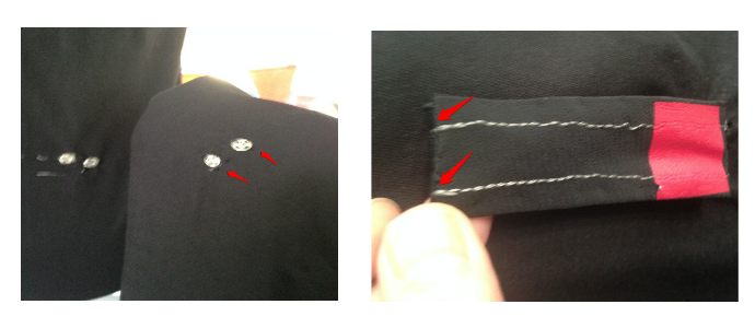
Connect the battery to some jumpers and bend the extremes with help of pliers until have a properly shape to sew them. Continue sewing to create two connections with some snap fasteners.

In another shirt sew at the same height the corresponding snap buttons (on the reverse side).

Iron the vinyl figures with Pacman shape matching with the path of the leds of the other shirt.leds of the other shirt.leds of the other shirt.leds of the other shirt. 
Vinil: https://drive.google.com/file/d/0B6qTJd3wtrO5b2NYTXdMQVQtckk/view?usp=sharing
We already have the shirts connected, we must now create a slider.
Cut 2 10×4 cm strips, sewing them together with conductive thread to be placed on the bobbin of the machine. I used textile vinyl to isolate. Sew the extreme with conductive thread making it match with the snap fasteners on the shirt without the circuit.
To create the button you must cut 3 squares of 4x4cm, iron a circle of textile vinyl in one of them to decorate, sew them and fill them with sponge cut to the same size.
In one of them, we will sew on one side a piece of conductive fabric of the same size and join it to the button, creating a sliding button that rides on the previous piece ensuring that the part with conductive fabric touches the stitching conductive thread thus the circuit is closed and the lights turn on.ensuring that the part with conductive fabric touches the stitching conductive thread thus the circuit is closed and the lights turn on.

Video:
BLOW
I would like to share with you my last personal work, I was inspired by Jie Qi, I have been following her for a long time and admire her talent. I hope you like it and especially thanks to Jie.
We started with the pattern, this time I cut it in the traditional way because the fablab laser is (60X30cm).
The fabric used is:
Chiffon 3m
Muslin 2m

Pattern:
https://drive.google.com/file/d/1A0JBQL_fc1HcGbTfx1Hm1R5tvc47unro/view?usp=sharing
Before sewing the dress is decorated with textile vinyl, in my case it is ironed at 167 degrees but look at your vinyl before ironing because not all are ironed at the same temperature.
I cut the vinyl with a 45ºC blade that is usually the basic one with these parameters:
Speed: 24
Power: 130
Iron at 167º (ask the seller, not all vinyls are ironed at the same temperature).

Design:
We sew all the pieces by machine, the circuit is sewn in the muslin to hide the components.
Circuit:
First I did tests with 3 leds.leds.


Code:
programa para soplar un sensor de sonido hc20 y que 6 leds en charliplexing sobre los pines 7, 6 y 5 se enciendan secuencialmente
El sensor tiene tres pines (vcc, gnd y valor de voltaje)
/* Hecho para charliplexing. Poner muchos leds en pocas entradas de arduino
Se conecta entre cada dos puertos de arduino un led en una posicion y el otro led al contrario
*/ const int sensorPIN = A3; pin de sensor de sonido conectado a arduino
const int sampleWindow = 50; Ancho ventana en mS (50 mS = 20Hz) (para el sensor de sonido) const int LED_1 =13; LED row 1 Definimos donde esta pinchado la primera linea de charlieplexing
const int LED_2 =12; LED row 2 Definimos donde esta pinchado la segunda linea de charlieplexing
const int LED_3 =11; LED row 3 Definimos donde esta pinchado la tercera linea de charlieplexing
const int LED_4 =10;
const int LED_5 =9;
void setup()
{
Serial.begin(9600);
}
void loop(){
unsigned long startMillis= millis();
unsigned int signalMax = 0; saber para que vale esto. Deben ser valores del sensor de micro
unsigned int signalMin = 1024;
int velocidad =500; velocidad de delay para la secuencia de leds
Recopilar durante la ventana
unsigned int sample;
while (millis() - startMillis < sampleWindow)
{
sample = analogRead(sensorPIN); leer el pin de el micro. Debe valer para establecer los limites automaticamente
  if (sample <1024)\\
{\\
if (sample> signalMax)\\
{\\
signalMax = sample;  // Actualizar máximo\\
}\\
else if (sample <signalMin)\\
{\\
signalMin = sample;  // Actualizar mínimo\\
}\\
}\\
}
unsigned int peakToPeak = signalMax - signalMin; Amplitud del sonido (lee el valor?)
double volts = (peakToPeak * 5.0) / 1024; Convertir a tensión
Serial.println(volts); imprime por el serial los voltios
if (volts > 4) { hecho por mi. Si el voltaje es mayor de 4 consideramos que esta activado
En caso de que sea positivo, va encendiendo cada uno de los leds por orden. Esto se puede convertir en funcion
/* Como establecer los cables en cada uno de los leds?
1) Ver el esquema del charliplexing
2) Establecer el pinmode de los cables donde esta conectado el led como OUTPUT. El resto de cables como INPUT
3) Los cables que usemos, pondremos el que corresponda a HIGH y el contrario a LOW
*/
turn on LED L1
pinMode(LED_1, OUTPUT); row 1 lo pone a OUTPUT y lo establece a 0
digitalWrite(LED_1,HIGH);
pinMode(LED_2, OUTPUT); row 2 lo pone a OUTPUT y lo establece a 1
digitalWrite(LED_2, LOW);
pinMode(LED_3, INPUT); row 3 lo pone a INPUT y lo establece a 0
digitalWrite(LED_3, LOW);
pinMode(LED_4, INPUT); row 3 lo pone a INPUT y lo establece a 0
digitalWrite(LED_4, LOW);
pinMode(LED_5, INPUT); row 3 lo pone a INPUT y lo establece a 0
digitalWrite(LED_5, LOW);
delay(velocidad=500);
turn on LED L2
pinMode(LED_1, OUTPUT); row 1
digitalWrite(LED_1,LOW);
pinMode(LED_2, OUTPUT); row 2
digitalWrite(LED_2,HIGH);
pinMode(LED_3, INPUT); row 3
digitalWrite(LED_3, LOW);
pinMode(LED_4, INPUT); row 3 lo pone a INPUT y lo establece a 0
digitalWrite(LED_4, LOW);
pinMode(LED_5, INPUT); row 3 lo pone a INPUT y lo establece a 0
digitalWrite(LED_5, LOW);
delay(velocidad=500);
turn on LED L3
pinMode(LED_1, INPUT); row 1
digitalWrite(LED_1, LOW);
pinMode(LED_2, OUTPUT); row 2
digitalWrite(LED_2, HIGH);
pinMode(LED_3,OUTPUT); row 3
digitalWrite(LED_3,LOW);
pinMode(LED_4, INPUT); row 3 lo pone a INPUT y lo establece a 0
digitalWrite(LED_4, LOW);
pinMode(LED_5, INPUT); row 3 lo pone a INPUT y lo establece a 0
digitalWrite(LED_5, LOW);
delay(velocidad=500);
turn on LED L4
pinMode(LED_1, INPUT); row 1
digitalWrite(LED_1, LOW);
pinMode(LED_2, OUTPUT); row 2
digitalWrite(LED_2,LOW);
pinMode(LED_3, OUTPUT); row 3
digitalWrite(LED_3, HIGH);
pinMode(LED_4, INPUT); row 3 lo pone a INPUT y lo establece a 0
digitalWrite(LED_4,LOW);
pinMode(LED_5, INPUT); row 3 lo pone a INPUT y lo establece a 0
digitalWrite(LED_5, LOW);
delay(velocidad=500); turn on LED L5
pinMode(LED_1, INPUT); row 1
digitalWrite(LED_1, LOW);
pinMode(LED_2, INPUT); row 2
digitalWrite(LED_2, LOW);
pinMode(LED_3, OUTPUT); row3
digitalWrite(LED_3, HIGH);
pinMode(LED_4,OUTPUT); row 4
digitalWrite(LED_4, LOW);
pinMode(LED_5, INPUT); row 5
digitalWrite(LED_5, LOW);
delay(velocidad=500);
turn on LED L6
pinMode(LED_1, INPUT);
digitalWrite(LED_1, LOW);
pinMode(LED_2, INPUT);
digitalWrite(LED_2, LOW);
pinMode(LED_3,OUTPUT);
digitalWrite(LED_3, LOW);
pinMode(LED_4, OUTPUT); row 4
digitalWrite(LED_4, HIGH);
pinMode(LED_5, INPUT); row 5
digitalWrite(LED_5, LOW);
delay(velocidad=500);
turn on LED L7
pinMode(LED_1, INPUT); row 1
digitalWrite(LED_1, LOW);
pinMode(LED_2, INPUT); row 2
digitalWrite(LED_2, LOW);
pinMode(LED_3, INPUT); row 3
digitalWrite(LED_3, LOW);
pinMode(LED_4, OUTPUT); row 4
digitalWrite(LED_4, HIGH);
pinMode(LED_5,OUTPUT); row 5
digitalWrite(LED_5, LOW);
delay(velocidad=500);
turn on LED L8
pinMode(LED_1, INPUT); row 1
digitalWrite(LED_1, LOW);
pinMode(LED_2, INPUT); row 2
digitalWrite(LED_2, LOW);
pinMode(LED_3, INPUT); row 3
digitalWrite(LED_3, LOW);
pinMode(LED_4, OUTPUT); row 4
digitalWrite(LED_4,LOW);
pinMode(LED_5, OUTPUT); row 5
digitalWrite(LED_5, HIGH);
delay(velocidad=500);
turn on LED L9
pinMode(LED_1, OUTPUT); row 1
digitalWrite(LED_1,HIGH);
pinMode(LED_2, INPUT); row 2
digitalWrite(LED_2, LOW);
pinMode(LED_3, OUTPUT); row 3
digitalWrite(LED_3,LOW);
pinMode(LED_4, INPUT); row 4
digitalWrite(LED_4, LOW);
pinMode(LED_5, INPUT); row 5
digitalWrite(LED_5, LOW);
delay(velocidad=500);
turn on LED L10
pinMode(LED_1, OUTPUT); row 1
digitalWrite(LED_1, LOW);
pinMode(LED_2, INPUT); row 2
digitalWrite(LED_2, LOW);
pinMode(LED_3, OUTPUT); row 3
digitalWrite(LED_3, HIGH);
pinMode(LED_4, INPUT); row 4
digitalWrite(LED_4, LOW);
pinMode(LED_5, INPUT); row 5
digitalWrite(LED_5, LOW);
delay(velocidad=500);
turn on LED L11
pinMode(LED_1, INPUT); row 1
digitalWrite(LED_1, LOW);
pinMode(LED_2, OUTPUT); row 2
digitalWrite(LED_2, HIGH);
pinMode(LED_3, INPUT); row 3
digitalWrite(LED_3, LOW);
pinMode(LED_4,OUTPUT); row 4
digitalWrite(LED_4, LOW);
pinMode(LED_5, INPUT); row 5
digitalWrite(LED_5, LOW);
delay(velocidad=500);
turn on LED L12
pinMode(LED_1, INPUT); row 1
digitalWrite(LED_1, LOW);
pinMode(LED_2, OUTPUT); row 2
digitalWrite(LED_2, HIGH);
pinMode(LED_3, INPUT); row 3
digitalWrite(LED_3, LOW);
pinMode(LED_4,OUTPUT); row 4
digitalWrite(LED_4, LOW);
pinMode(LED_5, INPUT); row 5
digitalWrite(LED_5, LOW);
delay(velocidad=500);
digitalWrite(LED_1, LOW);
digitalWrite(LED_2, LOW);
digitalWrite(LED_3, LOW);
digitalWrite(LED_4, LOW);
digitalWrite(LED_5, LOW);
}
}