Digital Bodies
This week's assignment was to create a mannequin using digital based techniques. Because of the complexity of the assignment, we were allowed to work in groups, so Eldy, Alexandra and I, managed to create our mannequin just in time.
The first step towards assembling the mannequin was choosing the techniques we were going to use. While brainstorming, the following ideas came up:
- Using composite materials
- Using interlocked slices in order to build the mannequin
- Using traditional sculpting techniques
- Thermoforming plastic
- Vaccum forming plastic.
- Cardboard folding
We decided to use a mixture of these techniques, in order to experiment and learn how different materials interact with each other. You should probably check out Ale's page if you want to see how the mannequin was designed and why it was designed like that. The final sketch of the mannequin can be seen in the following picture:
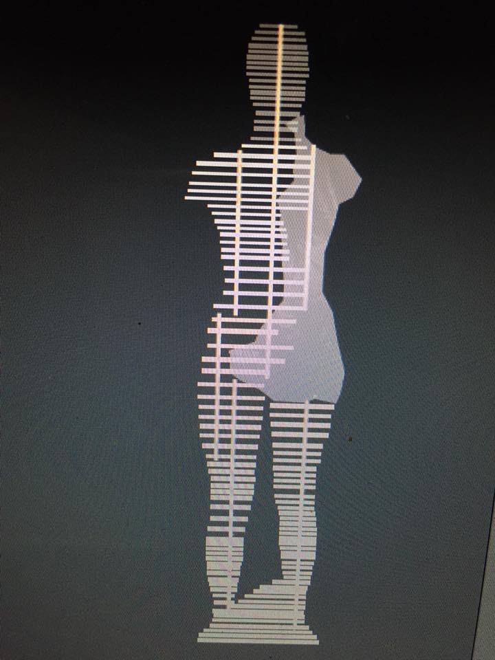
Basically, this mannequin will consist of interlocked slices of 12 mm plywood and 6 mm acrylic plastic. On the torso, it will be covered in folded cardboard, which will then be covered with a composite. The process for obtaining the model is as follows:
Step 1: 3D scanning
As part of the assignment, we were required to scan our bodies and generate the mannequin based on ourselves. Because we wanted the scanned model to as accurate as possible, we contacted one of Alexandra's friends, who works as a mannequin maker. She helped us take Alexandra's body measurements using red ribbons.
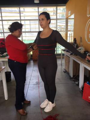
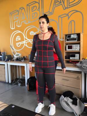
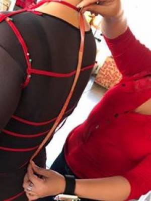
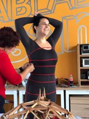
After the mannequin is completed, we'll use the measurements obtained with this process, so as to make sure that our model is accurate and true to Alexandra's body.
As part of our investigation, we tried 3 different scanning procedures:
- Photogrammetry
- Laser Scanning
- Visual Scanning
Photogrammetry
This was the least successful of the techniques we tried out. It consists of taking several photographs from your phone and using an app to combine them, generating a 3d model of a person or object. We use the Scan3D app (only available for Android), to try and generate a model of Alexandra's body. Despite all of our best attempts, we never managed to obtain a result we could use in our project, thus, we ended up using different techniques.
Laser Scanning
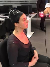
Laser scanning was my favourite technique, and, if it weren't for Ale's clothes, it would have been the best one. In order to perform this process correctly, it was necessary for us to cover Ale with special reflecting targets, which would serve to orient the scanner during the process.
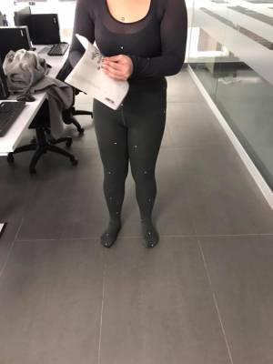

It was also necessary for Ale to cover her head with a swimming cap so that the scanner could work properly since it is unable to detect hair. She was not happy about it.
When she was finally full of targets, it was time for us to start scanning. The first step was calibrating the scanner. In order to do so, we needed the scanner kit, which consists of a box with a pre-arranged set of targets.
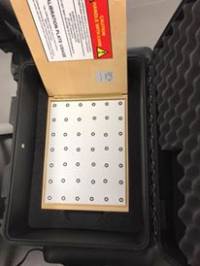
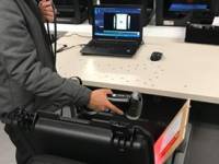 Once the scanner's been calibrated, the next step is to scan the targets that have been placed all over the subject, or, in this case, Alexandra. This process must be done slowly, so as to not lose sight of any of the targets.
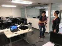
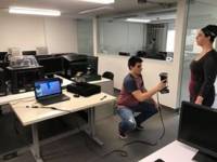

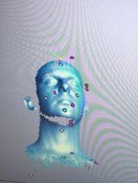
Once this was done, we started scanning the body. This was the part where we had the most trouble. Because of the color of her clothes, it was impossible for the scanner to obtain any data. The scanner was able to obtain images of her skin, like her face and neck, but once it reached the rest of her body, nothing was sent to the computer.
So, in order to test our theory, we decided to scan my leg, to see if my clothes would be suitable for scanning. Yes, they were. The scanner did capture my body, but because my clothes were too loose, the image would not be appropriate.
Thus, we had to proceed to the next technique.
Visual Scanning
For this process, we used a Sense3D scanner. It captures low-quality images of a specific body, turning it into a virtual 3D object.
If you want to learn more about this process, you should check out Eldy's page since she was in charge of the process. This process, however, was not problem free, and there was a lot of trial and error before we could finally complete the scanning.
Step 2: Editing the mesh and obtaining the patterns
From scanning, we obtain quite a defective mesh. Using mesh-mixer, Eldy managed to correct it, again, check her page. Once it was finished, she handed it over to me so that I could perform two major tasks:
- Obtain the folded panels and interlocked slices from Slicer.
- Edit the scanned hand, and obtain a model similar to this one:
When trying to design the hand, I used Rhino WIP, and its plugin Panelling Tools, in order to generate different patterns over the hand's surface and obtain my 3d printed hand. To do so, I used the following tutorials as guidance:
I did manage to generate some interesting patterns on regular surfaces like spheres and cylinders, as it can be seen in these images:
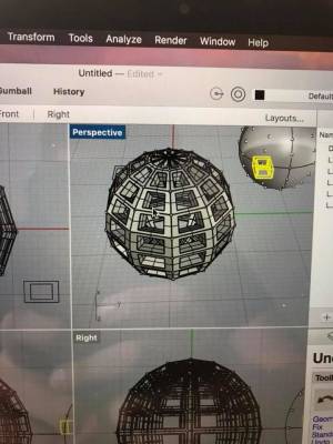
This was pretty easy since I only needed to use 4 commands:
- PtGridSurfaceDomainNumber
- Group
- PtOffsetPoints
- PtPanel3DCustom
So naturally, I thought obtaining the hand would be pretty easy as well. I was wrong. Because of the irregularity of the surface, the computer could not obtain a pattern around the hand, except for a couple of segments, so I never managed to generate the hand I was looking for. Even though we never managed to obtain the hand, after the assignment was completed, Eldy and Ale suggested 2 different approaches for generating this solid later in the future.
- Using the hand's mesh (not surface) to create a pattern, and extrude it, thus obtaining the hand's “natural” look.
- Reducing the hand mesh, and using “Mesh2Nurb” in Rhino, to obtain a surface and then follow the steps
I mentioned earlier, simplifying the process.
So, I didn't complete the hand, but there was still one other task ahead of me. The 3d scanned model we obtained was this one:
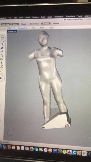
I imported this STL into Slicer for Fusion 360, and, set out to obtain both the folded cardboard and the interlocked slices. I started with the folded panels.
The first step was defining the parameters. Because the panels were cut in a Speedy 360 laser cutter, we needed to establish the cutting area, which was 1000 x 600 mm. Once this was set, and after a LOT of trial and error, we managed to obtain the optimal number of panels needed to make the mannequin, based on the number of vertexes and faces of the body. The optimal combination was 540 vertexes and 1080 faces. I do not guarantee that these numbers will work for everyone, so you should keep trying until the software is able to give a number which will not generate building errors.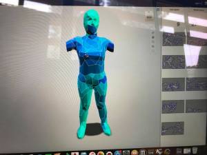
Given how most of our mannequin was going to be made out of interlocked slices of plywood and acrylic, we chose only 5 panels to cover half of the torso and most of the back. These were panels 18, 19, 21, 25, and 27.
Afterward, I set out to obtain the slices. Again, after a LOT of trial and error, the optimal number of panels was set to 7 panels for the Y-axis, and 80 panels for the Z-axis. Ale pointed out, however, that a structure of these characteristics would be extremely heavy and unstable, so we decided to delete some of the slices between the knees and the shoulders. The mannequin started looking like this:
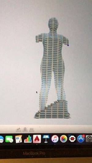 and ended up looking something like this:
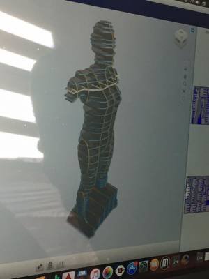
Before we could cut, though, it was necessary for us to determine how the pieces locked with each other, and whether or not we had to manipulate the dimensions of the cuts. You should check Ale's page to see how the testing was done.
Anyway, once the parameters were set, we downloaded the file in DXF format and opened them in AutoCAD to edit them. Due to the different materials we used, we had to produce 3 different files. The first one contained all of the pieces which were to be cut in plywood using the shopbot machine, and that didn't need any sort of editing. The second file contained all of the pieces to be cut in acrylic with the Speedy 360, that did not need editing. Finally, the third file contained the remaining pieces, which were supposed to be cut in the shopbot, but needed to be edited because of the change of materials. That is to say: because the acrylic was 6 inches thick, but the plywood was 12 inches thick, some of the vertical pieces had holes of two different dimensions. But, Slicer does not allow the user to use different materials when generating the slices. Thus, two files where generated, one for every dimension, and these files were mixed afterward.  The image shows how some of the pieces have holes of different sizes, this is necessary in order to accommodate both the plywood and the acrylic.
Step 3: Assemblying
Unfortunately, because of my midterm exams, I could not stay long enough to help laser cut most of the Plexiglass parts, but I did manage to return for the assembling process. Thankfully, Eldy had tested the material before, and she adjusted the design so that the parts would fit properly. It was a tiring job though, due to the friction created between the pieces of plywood. But, after the base was done, the rest of the pieces fit smoothly. The Plexiglass was super easy to fit with the plywood. This is the result:
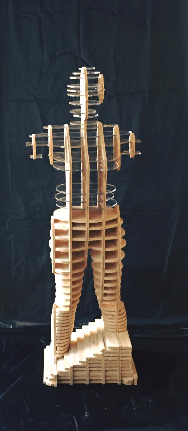
All things considered, I think our mannequin is pretty close to what we wanted to achieve.
Here are the Slicer and AutoCAD files. I think these are all of the files, but contact me if it's incomplete.

