Week 12: Skin electronics
This week's assignment was to use skin electronics to create a carnival mask with neopixels. As I was uncertain about putting electric circuits directly on my skin, I decided to make a mask from material with the neopixels, microcontroller and external batteries. To download the files, visit: https://oscircularfashion.herokuapp.com/project/-L6SX_pAbREawjWZ3ju8
First experiments
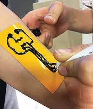
Firstly as a group, we explored creating circuits on the skin with Bare Conductive ink. We used Adriana's pre-designed circuit and cut this cut as a stencil in the vinyl cutter using heat transfer vinyl.
We put the stencil on the skin and used the conductive ink to fill in the traces. We waited for the ink to dry before peeling off the stencil. However, when peeling off the stencil, the some of the ink stuck to the stencil and therefore didn't paste onto the skin. We tried to salvage this as much as possible by using water to help detach the ink from the stencil.
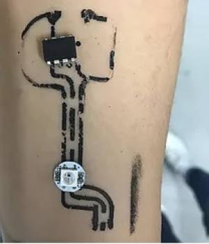
Once the stencil was fully off, we measured the conductivity with the multimeter. Because the ink tended to crack when it was dry on the skin, the connection was disrupted and thus did not conduct. However, the conductivity was fine in places where it was not cracked.
Production of carnival mask
I wanted to create a masquerade mask rather than design one from scratch, therefore I searched on Google for images that I liked. I found the image below which I vectorised using Photoshop.

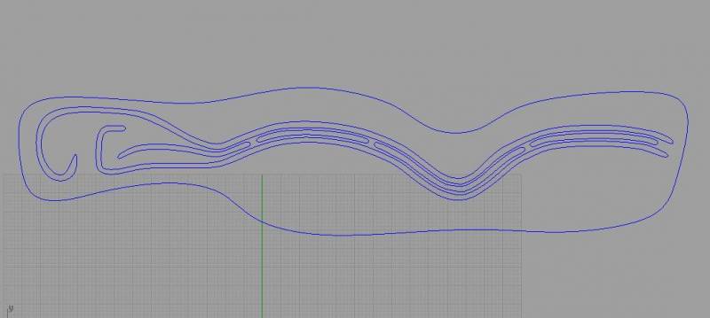
I put the image in Rhino to tidy up the design and create space for the neopixels above the eyes and for the microcontroller on the left hand side. I also created slots on the sides for the strap be fitted.
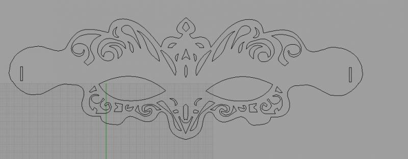
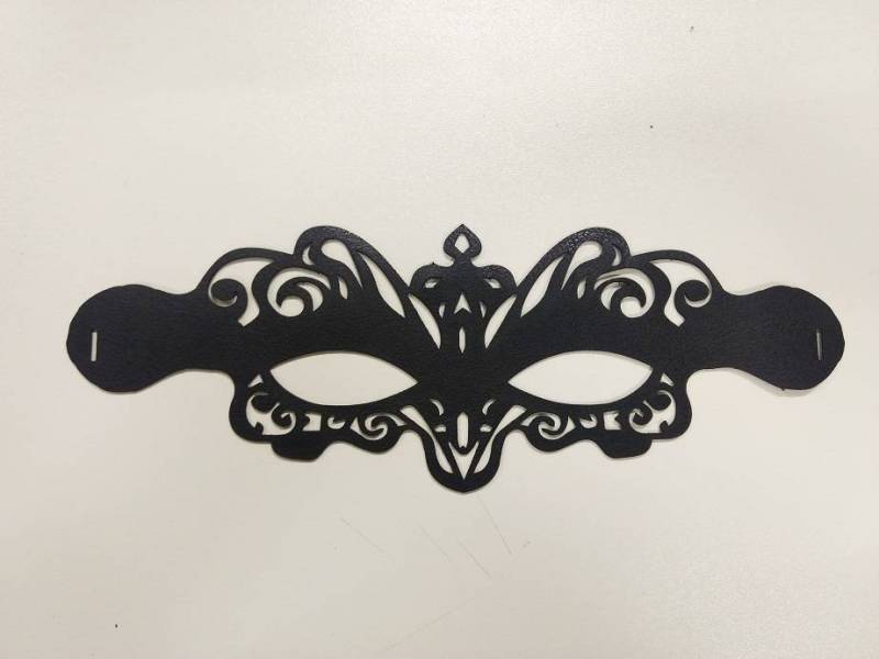
I then laser cut the mask in fake leather, using these settings for the big Epilog laser cutter: Speed 100, power 45, frequency 50.
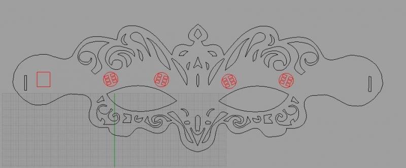
Going back to the design in Rhino, I wanted to create traces with conductive ink and to do this, I had to create a stencil. Therefore on a different layer in Rhino, I created the components and placed them where I wanted, to act as a guide. For the battery, I planned to use a battery holder that would be attached to the strap, therefore I did not include this in the design.
In another layer, I then created the traces joining up the GND and VCC of all the neopixels to the corresponding legs of the microcontroller, and the Vin and Vout of the neopixels - making sure that they were not continuous connections like the GND and VCC.
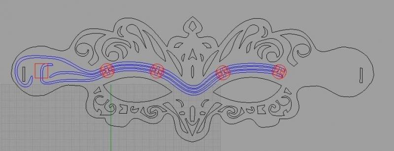
I then created a stencil out of the traces and used the Silhouette program to prepare it for cutting in the plotter cutter.
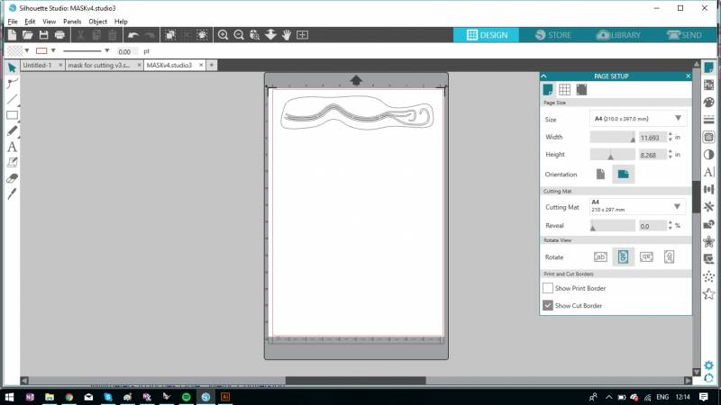
In Silhouette, I chose A4 for the page size and cutting mat, and portrait orientation. I had to make sure the size of the design was correct therefore I measured the design in Rhino and specified this in Silhouette in inches as the program deals only with inches.
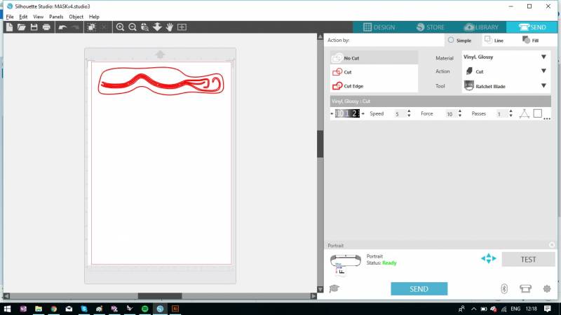
To prepare the design for cutting, I selected the 'Send' tab and specified my material (glossy vinyl) and the 'cut' action. The program prepared the cutting details and advised me to change the cutting tool depth to 1 - which I did using the mechanism on the plotter cutter machine. I then selected 'Test' to see if the cut was ok.
After a successful test, I sent the design to be cut in the plotter using glossy transfer vinyl.
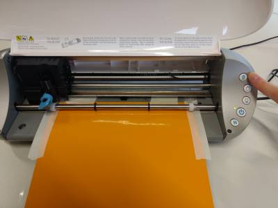
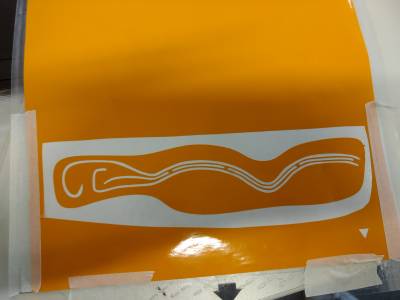
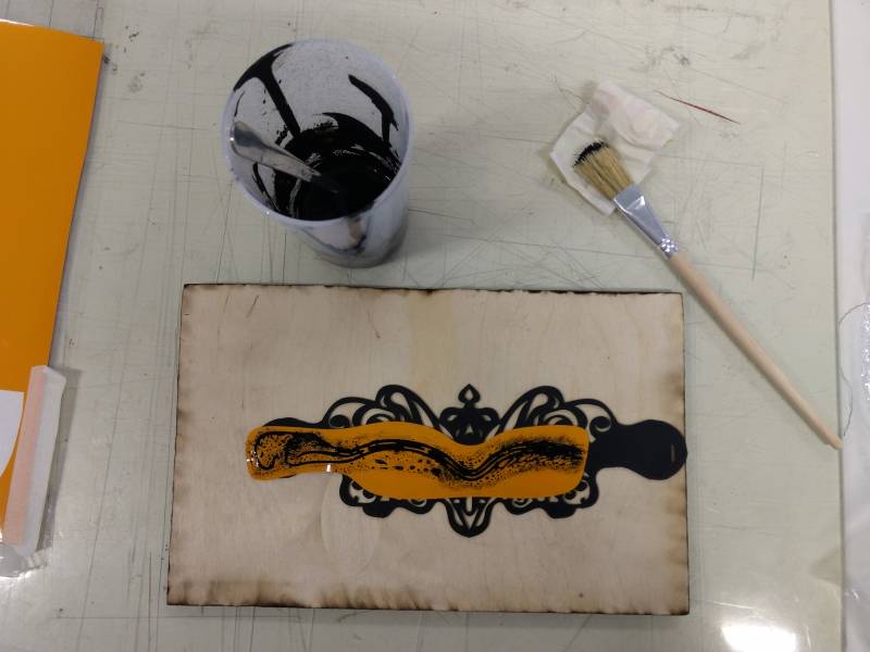
Because the details of the stencil were delicate and getting the right position was important, I used masking tape to help me transfer the stencil onto the mask.
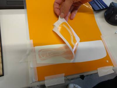
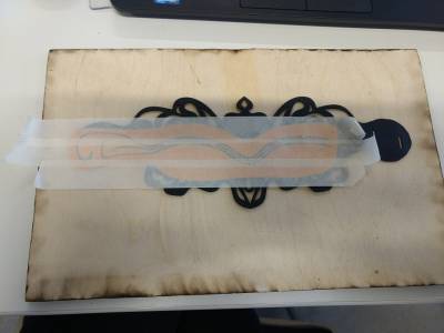
Adriana informed me that the conductive ink was not as conductive as desired and that it the conductivity should be reinforced by making some traces using conductive thread. Based on this advice, I hand sewed the traces using a running stitch.
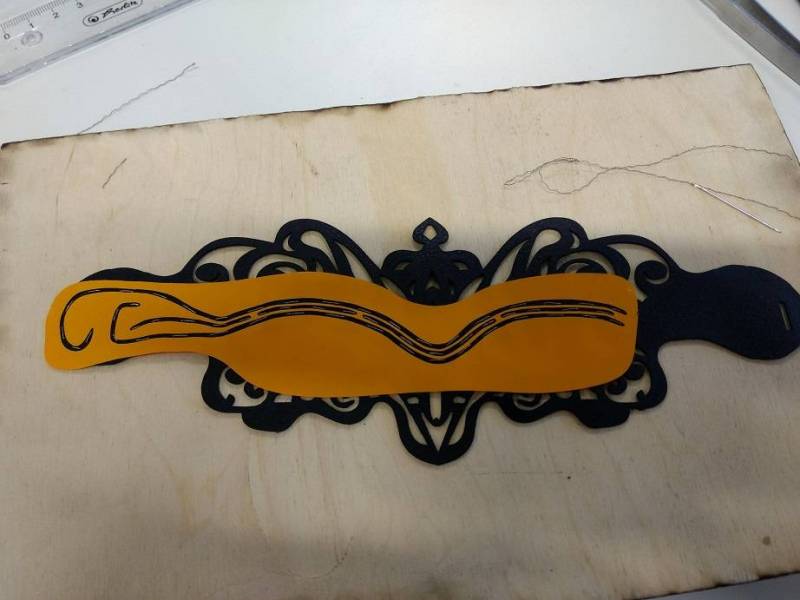
After sewing, I used Bare conductive ink to paint over all the traces in the stencil and waited for 30-40 minutes to dry. Using a multimeter, I tested the connections and found that it was conductive where the thread was placed, but there was very little conductivity where there was no thread and only conductive ink.
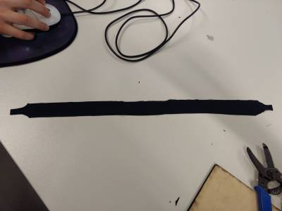
I created a strap for the mask using a black lycra material, inserted the ends through the pre-cut holes and secured the ends with normal thread.
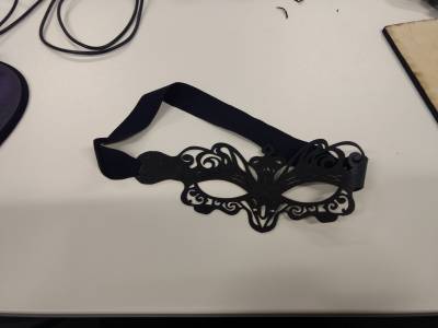
I then used the conductive ink to paste the 4 neopixels onto their designated places on the mask, taking care to ensure the Vin and Vout were separate and also to place the LEDs on the traces.
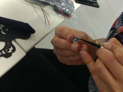
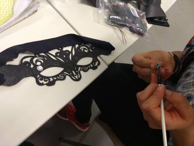
Once all 4 neopixels were in place, I tested them by connecting them up to the computer with crocodile cables and uploading the Adafruit neopixel sketch. The first two LEDs worked fine but the second two LEDs did not work. We guessed that this was due to insufficient connections to the traces or bridged connections.
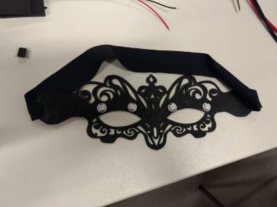
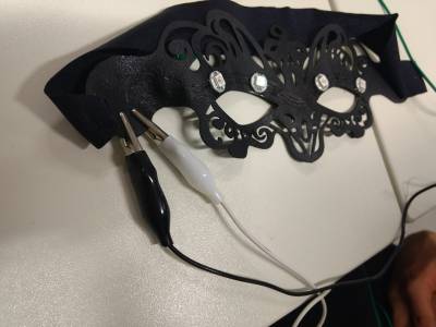
To solve this problem, I removed the 2 neopixels and used another process to connect them onto the mask. Before starting, I first tested them to make sure that the LEDs were working, and found that they were. I then soldered wires onto the neopixels and put them in place on the mask using normal thread to make sure the wires were touching the traces. I tested continuously the connections using a multimeter and was satisfied that the LEDs were connected well.
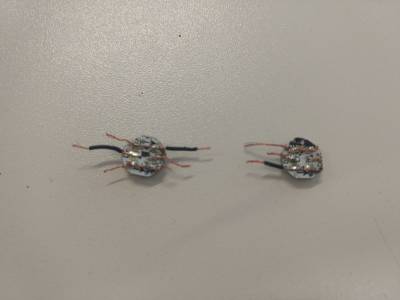
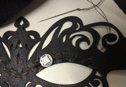
I then tested the neopixels again with the computer but the last two lights were again not working. Although my test with the multimeter seemed to show everything was fine, there was obviously still a problem, perhaps I made some bridges with the wires when soldering as it was difficult to contain all the fibres of the wires together.
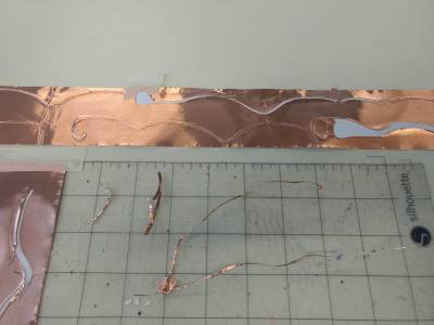
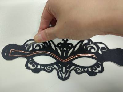
I therefore needed a different method of fixing the neopixels. I decided to use copper tape to print out the traces I had made in Rhino. I first stuck a piece of copper tape onto the fake leather to see if it held ok and was satisfied that it did. I then went ahead and printed the traces using the big vinyl cutter.
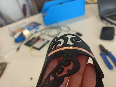
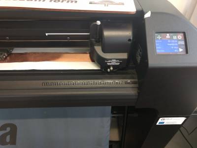
A problem with cutting out the traces with copper tape and the vinyl cutter was that the cutter dragged the cut pieces when moving the head to cut new pieces. To minimise this effect, I put all the traces in a single line so that the cutter did not need to revisit the same area to cut further pieces. This worked a lot better.
After cutting the traces, I had to laser cut a new mask - given that the old mask was now very messy with conductive ink and threads everywhere. When I had my mask, I took out the copper traces and stuck them in place onto the mask.
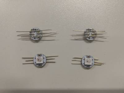
I decided to solder the neopixels onto the copper tape to ensure a good connection, to do this, I had to first solder wires onto each pad. This time I used a thicker wire that consisted of one piece, rather than many fibres like the previous wire I used. The single wire piece was much easier and faster to solder.
After soldering wires onto all the pads of the neopixels, I then trimmed the wire legs and soldered them onto the copper traces.
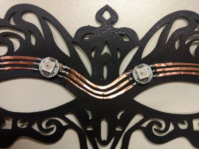
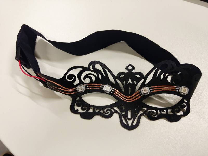
Once all four of the neopixels were soldered on, I tested them with the computer and found that they worked well.
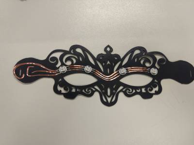
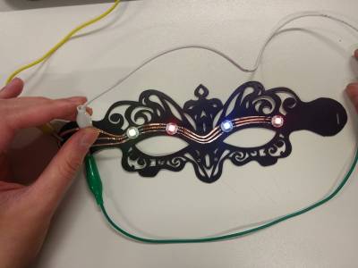
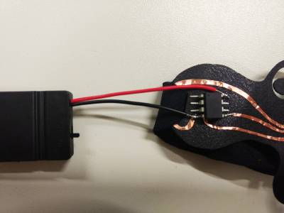
I then programmed the ATTiny 85 with the Arduino as ISP programmer using the Adafruit neopixel sketch. Once programmed, I soldered the ATTiny into place on the mask.
I also soldered the power and ground of a battery holder containing 2 CR2032 coin batteries (6V altogether) to the VCC and GND of the ATTiny.
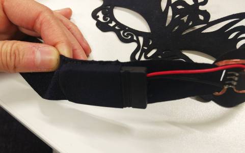
I removed the strap from the old mask and placed it on the new mask. I added a sleeve on the strap for the battery holder to slip into.
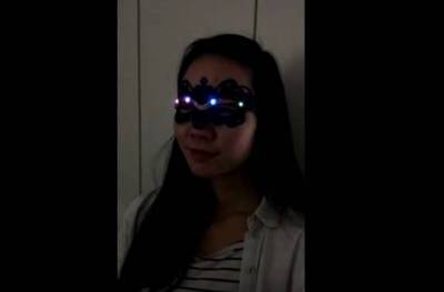
The Finished Product

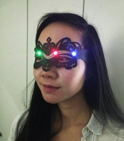
The neopixels on the mask worked well and it was fully portable.
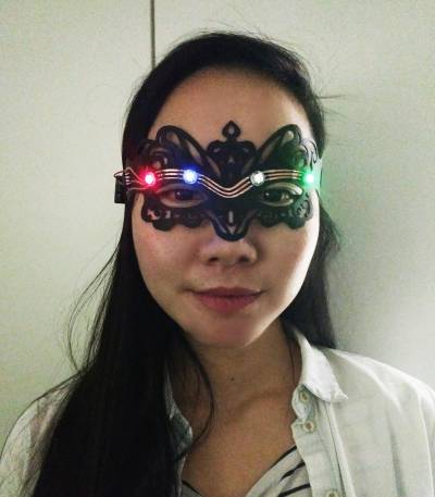
Here is a video of the neopixels working:
