Week 5: E-textiles & wearables I
For the project this week, it was necessary to understand a few fundamental things about electrical circuits:
- Voltage - is the the force or electrical pressure. This is measured in 'volts'. The short symbol is V.
- Current - is the quantity of electrons passing through a given point. This is measured in 'ampere'. The short symbol is I.
- Resistance - is the resistance to electrical flow in conductors/materials.This is measured in 'ohms'. The short symbol is R.
And an important calculation to remember is Ohm's Law: V = I x R (an example of an application of this law will be presented later).
A high resistance in materials means that it is less conductive of electricity, and a low resistance in materials means that it is more conductive. When a stretchy material is stretched, it will be more conductive - this is because the fibres have a straighter path and so the electrons can flow more easily.
Initial experiments
We started this week by testing the resistance of various conductive fabrics with multimeters. I made sure that the nodes of the multimeter were always 10 cm apart when testing different fabrics - in order to keep the conditions the same. This exercise showed that it is good to know how conductive different materials are so that you can choose the most suitable one, based on how much conductivity you need.
We also experimented with using pull up resistors to regulate the voltage in simple circuits. We used Ohm's Law to calculate how much resistance we needed. I had a 3V battery and a 2.2V LED light, therefore needing to compensate 0.8V in my circuit (3V - 2.2V). I measured with the multimeter that the current was 0.02 amps. We then calculated using Ohm's Law that I needed 40 ohms to regulate the circuit and used a pull up resistor of 40 ohms in my circuit.
Additionally, we received an introduction into arduino. We used a breadboard to connect an LED and pull up resistor into an electrical circuit. The arduino had to be connected to the computer via a USB cable in order to receive power for the circuit.
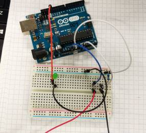
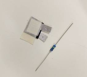
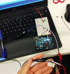
We also gained an overview of using the downloadable arduino software to read values and program the arduino. For this, we created a 'pressure sensor' - which contained 2 layers of foil, and in between the 2 layers - a piece of semi conductive carbon material which creates varying pressure when pressed. This sensor needed to have protruding tabs on the foil so that the alligator clips could be connected. We used the breadboard to connect together the pressure sensor, an LED. and a pull up resistor. We had to connect one wire from the pressure sensor to the analogue value A0 port in the arduino - this allowed us to read the values of the sensor using the program. We were also shown how we could program the arduino to make the LED blink at specific intervals - this involved using the 'blink' code in the program and sending the data to the arduino.
Incorporating LEDs and buttons in fabric
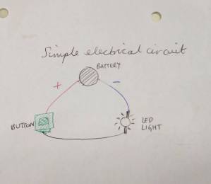
Before using fabric, we made simple electrical circuits using an LED, a battery, alligator clips and a 'button' that we created ourselves. The button consisted of a layer of non conductive fabric with a hole cut in the centre, sandwiched between 2 layers of conductive fabric:
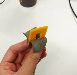
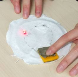
When this button is integrated in a circuit, it will complete the electrical circuit when it is pressed and the 2 layers of conductive fabric touch - thus creating the circular electrical connection, which then lights up / turns on the LED.
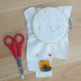
After experimenting with alligator clips, we created the same simple circuits with fabric and conductive thread. We sewed the thread and the LED into the circuit by hand and we had to create a 'pocket' for the battery to sit inside:
The assignment
For this week, I chose to create an LED circuit incorporating a sensor. I integrated this into a choker necklace because I was keen to create a wearable artefact for this assignment. The choker used a parallel circuit with 4 LEDs, and the traces were created using conductive thread and the embroidery machine and sewing by hand. The sensor was a metal popper button which disrupted the circuit when the choker was unworn (and the button was left open), and which completed the circuit when the choker was worn around the neck (when the button was closed).


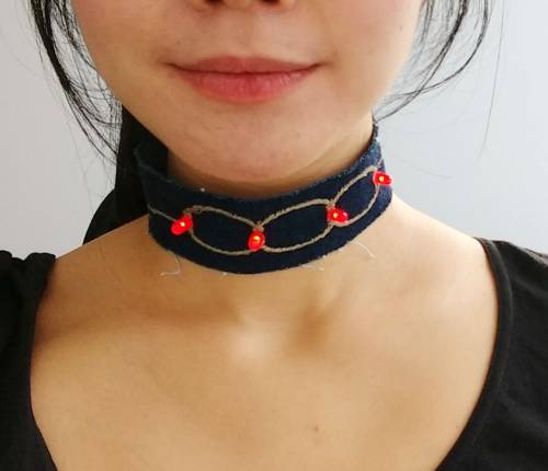
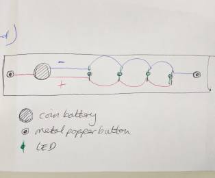
I wanted to design a parallel circuit that would look nice on a choker. I had different ideas but found them difficult to put into a parallel circuit as it is important in a parallel circuit to keep the positive and negative wires separate. Finally, I came up with the design in the picture below (first image).
I was keen to use the embroidery machine as it was new for me, I liked the finished result from example work, and it also saved a lot of time. To use the embroidery machine, I first drew the image I wanted to embroider in Illustrator. Then I imported the illustration into the PE Design program which is the designated program for the embroidery machine, and I took the following steps:
- Changed the canvas size to 180mm by 130mm - because this would be the size of the hoop I would use.
- Converted the image into stitches using the 'punch' function and chose zig zag stitches.
- Saved the file in .pes format onto a USB stick.
- Prepared the material to be embroidered - applied strengthening sticky paper to the back of the material, fixed the 2 parts of the hoop to the material and pulled the material tautly through the hoop (so that it made a drum noise), placed the hoop onto the machine.
- Inserted the USB stick into the embroidery machine.
- Chose the correct canvas size in the machine.
- Chose the desired thread (I chose the most conductive thread).
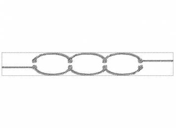
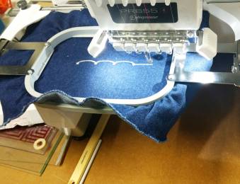
Once the embroidery was done, I completed the choker by hand. This involved:
- Measuring the material around my neck and cutting the strip suitable for my size.
- Fixing in the LEDs by piercing them through the material - the positive leg (longer leg) to the positive thread and negative leg to the negative thread.
- Sewing extensions from the embroidered section towards the battery using conductive thread.
- Creating a 'pocket' for the battery and sewing the positive section on top and the negative section behind.
- Sewing the metal popper buttons with conductive thread - one part of the button at one end connecting to the positive thread, and the other part of the button at the other end connecting the negative thread.
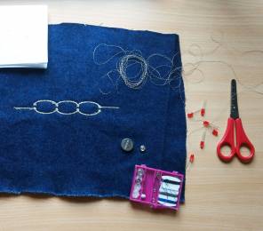
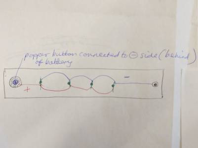
I followed my drawing above and when I came to sewing the metal popper buttons, I realised there was a mistake in my circuit. My intention was to create the connection only when the buttons were connected, however, in my original drawing, the parallel circuit is flowing regardless of whether the buttons are connected or not. The button was not disrupting the circuit at all. Therefore, I had to think of a way to achieve what I wanted. I thought about putting the button in the design, between the traces and the battery, but I thought this would look messy. Finally, I figured out that I could sew a button touching the back of the battery - which would be the negative button, and which would only become connected when the other button from the other side (which was connected to the negative threads) and complete the circuit. The positive thread would be connected to the front of the battery, as expected. This diagram illustrates this:
Problems
An impact of the problem mentioned above was that I had to undo some of my sewing and place the battery in a different place. I also needed more space on the choker to do what I needed, but as I had already cut the choker to size, I had to sew an extra piece onto the choker to fit my amended design.
The first use of the embroidery machine created the image smaller than expected. I realised this was due to the fact that I needed to select the correct canvas size on the machine itself, as well as in the PE Design program. Therefore, once I selected the corrected size, the machine produced the expected result.
Final thoughts
It was very pleasing to produce a circuit integrated in material that worked. I found some concepts difficult to understand, especially with the arduino and programming. This shows me that I need more practice with the arduino.