SOS- System of Support
My final project is called “SOS- System of Support” and I am working together with Melissa Disimino.

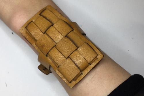
The System of Support is meant to be an armband for elderly people.
Nowadays when large families with many members that are composed of several generations are becoming fewer and fewer, we are always worried how are our grandparents doing specially if they are without their partner and leaving all alone.The armband will be able to detect a fall (which could be caused by health problem or even accidents in the house) and make a call for help to one of the closes person of the person wearing it. The armband is customizable and gives security to the person wearing it and also to their familiars.

Technical Set up

We are using the gyroscope ADXL 345 to detect a fall and then it will give a signal through Arduino Mini to the Esp and the Esp will send a message or make a call to an other person.
The Design
We decided do create adjustable designs since we don't know the final size of the technical set up.
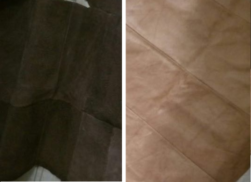
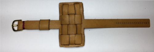
Materials and Design We chose to work with leather since we thought that would be nicer for different skins. Since for this projects Melissa was inspired from her grandmother, we decided to use an old leather in her possession so that would have a bigger sentimental value. 
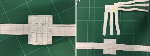
Melissa had the idea to create a wristband with a weaving technique so she tried the design first in paper and then we used synthetic leather for the prototype.


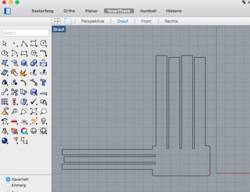
This design is created in Rhino and Grasshopper using slicer in oder to be easy adjustable for different sizes and then laser cutter.

We liked the design of the prototype but there were some aspects to change:
- Number of parts (the prototype consisted of many single parts)
- Layers (the idea was to choose a design that was as thin as possible, but the prototype had about five layers)
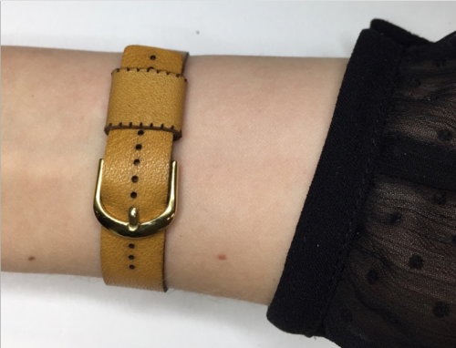
- Lock (To close the bracelet you needed a second person or a lot of patience)
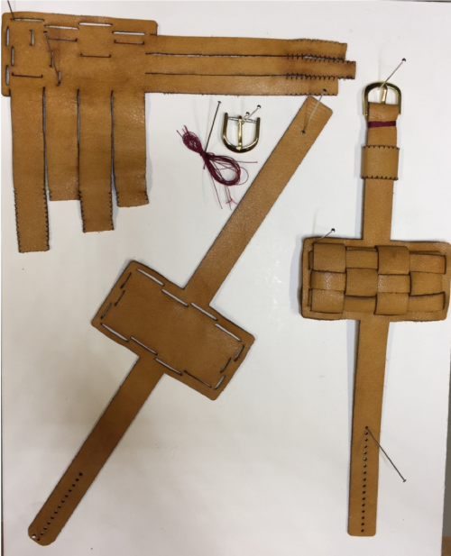
Then the design changed in the following stages
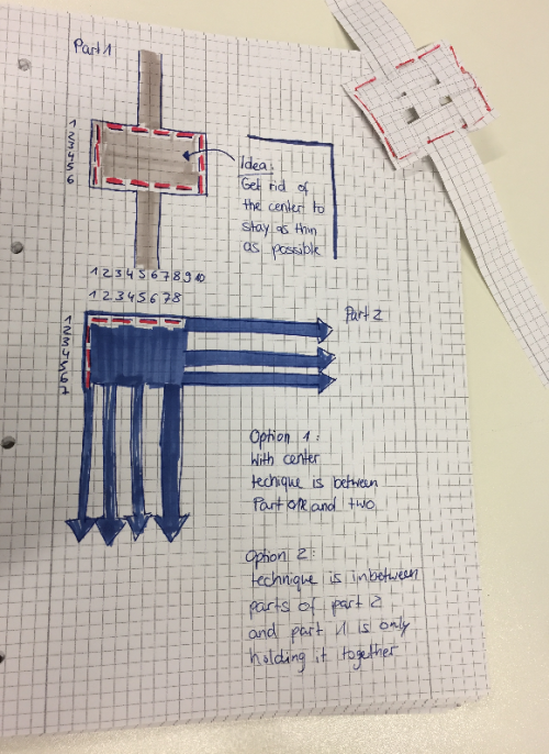
One part is the base of the bracelet. Part 1 has two long straps that will build the lock of the bracelet later on. Therefore, the straps have tiny holes in them. The single hole on the left side holds the lock, the number of holes on the right side adjust the size of the bracelet. In the middle of part 1 there is the frame for the weaving pattern. Part 2 goes through the slots in here.
Part 2 builds the pocket for the technical set up by weaving its 7 straps through part 1. The straps have incisions which allow them to stay in the slots in the center of part 2.
Part 3 will hold the strap of part 1 when the bracelet is closed. Therefore, it is sewed together.

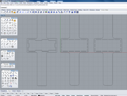


Properties to the laser cutter : speed 30, power 100

That leather is 0,1 mm thick. The colour is a light brown, maybe camel. It has two different textures: flat and sued leather.
The leather for the final design was sticked to a wooden plate, so the material would not move and the design would be as precise as possible. Before putting it together one essential step was the cleaning process.The progressed leather smelled really strong. So Melissa cleaned it carefully using different cleaning tools and leather care.


Final set up and code
We are using the gyroscope ADXL 345 to detect a fall and then it will give a signal through Arduino Nano to the Esp and the Esp will send a message or make a call to an other person.
Gyroscope to Arduino Nano:
SCL-A5
SDA-A4
GND-GND
VCC-3.3V or 5V
ESP to Arduino Nano:
pin 14-pin 2
GND-GND
Battery connected to pull up
VCC-VIN
GND-GND
VOUT of Pull up connected to 5V of ESP and VCC of Arduino nano
GND of pull up connected to both GND of ESP and Arduino nano
At first we thought that the Esp will communicate with the phone through Twilio. Twilio is a cloud communication platform which allows developers to programmatically make and receive phone calls and text messages using its web service APIs. But the esp wasn't responding properly to twilio connections. To make the esp communicate with twlio in order to make the call was unsuccessful for me.
After some researches we found a tutorial using the IFTTT web based service which allows to create chains of simple conditional statements called applets. We created an applet and connected to phone number. Every time the applet is triggered will send a SMS to a phone.
So every time the gyroscope will detect a fall, pin 2 of the arduino will communicate with pin 14 of the esp then the esp will trigger the IFTTT applet which will send an SMS.
/*
    ADXL345 Triple Axis Accelerometer. Free Fall Detection
    Read more: http://www.jarzebski.pl/arduino/czujniki-i-sensory/3-osiowy-akcelerometr-adxl345.html
    GIT: https://github.com/jarzebski/Arduino-ADXL345
    Web: http://www.jarzebski.pl
    (c) 2014 by Korneliusz Jarzebski

This code is changed from the original one created from Jarzebski.
*/

#include <Wire.h>
#include <ADXL345.h>

ADXL345 accelerometer;
int fall = 2;
void setup(void)
{
  Serial.begin(9600);

  // Initialize ADXL345
  Serial.println("Initialize L3G4200D");

  if (!accelerometer.begin())
  {
    Serial.println("Could not find a valid ADXL345 sensor, check wiring!");
    delay(500);
  }

  // Values for Free Fall detection
  accelerometer.setFreeFallThreshold(0.35); // Recommended 0.3 -0.6 g
  accelerometer.setFreeFallDuration(0.1);  // Recommended 0.1 s

  // Select INT 1 for get activities
  accelerometer.useInterrupt(ADXL345_INT1);

  // Check settings
  checkSetup();
   pinMode(fall, OUTPUT);
   digitalWrite(fall, LOW);

}

void checkSetup()
{
  Serial.print("Free Fall Threshold = "); Serial.println(accelerometer.getFreeFallThreshold());
  Serial.print("Free Fall Duration = "); Serial.println(accelerometer.getFreeFallDuration());
}

void loop(void)
{
  delay(50);

  // Read values for activities
  Vector norm = accelerometer.readNormalize();

  // Read activities
  Activites activ = accelerometer.readActivites();

  if (activ.isFreeFall)
  {
    Serial.println("Free Fall Detected!");
    digitalWrite(fall, HIGH);
  delay(450);
    digitalWrite(fall, LOW);

  }

}
The upper code is used for the free fall detection. Is based on an online documentation, the links for this documentation are on the top comment of the code but it has changes from the original one. The second code used for the call is the coming one.
#include <ESP8266WiFi.h>
#include <WiFiClientSecure.h>
#define GPIO_PIN 14

const char* ssid = "FabLab2";
const char* password = "FabLabKaL!";

const char* host = "maker.ifttt.com";
const int httpsPort = 443;

int buttonState = 0;         // variable for reading the pushbutton status

void setup() {
  Serial.begin(9600);
  Serial.println();
  Serial.print("connecting to ");
  Serial.println(ssid);
  WiFi.begin(ssid, password);
  while (WiFi.status() != WL_CONNECTED) {
    delay(500);
    Serial.print(".");
  }
  Serial.println("");
  Serial.println("WiFi connected");
  Serial.println("IP address: ");
  Serial.println(WiFi.localIP());
wifiSetup();
pinMode(GPIO_PIN, INPUT);

}

void sendSMS (){
    WiFiClientSecure client;

  Serial.print("connecting to ");
  Serial.println(host);
  if (!client.connect(host, httpsPort)) {
    Serial.println("connection failed");
    return;
  }
  String url = "https://maker.ifttt.com/trigger/HELP/with/key/hRKfgrkOS4df5CLYDaOa29UMukWV1FHxd6GqnQEQa0t";
  Serial.print("requesting URL: ");
  Serial.println(url);

  client.print(String("GET ") + url + " HTTP/1.1\r\n" +
               "Host: " + host + "r\n" +
               "User-Agent: BuildFailureDetectorESP8266\r\n" +
               "Connection: close\r\n\r\n");

  Serial.println("request sent");
  while (client.connected()) {
    String line = client.readStringUntil('n');
    if (line == "r") {
      Serial.println("headers received");
      break;
    }
  }
  String line = client.readStringUntil('n');

  Serial.println("reply was:");
  Serial.println("==========");
  Serial.println(line);
  Serial.println("==========");
  Serial.println("closing connection");
  }

void loop() {
  buttonState = digitalRead(GPIO_PIN);
  if(buttonState == HIGH){
    sendSMS();
      Serial.println("SMS Sent");

    buttonState = LOW;
    delay(500);
  }}
To protect the technical set up in the bracelet, a box will be around it.
The scetch for the box was created in Fusion 360. The box consists of two parts, the box itself and a cover.
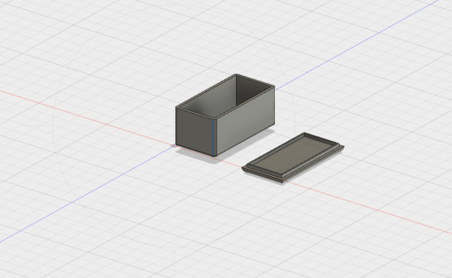

The box was then printed with the professional high definition 3D printer ProJet.

To create this box the printer makes use of a special technique. The actual print is covered in a wax during the process. By heating up the output of the printer the wax will melt and the box will show up.


In the end the technique is put in the box and the box is hidden in the bracelet. Unfortunately we realized that the box did not suit the final bracelet made at an earlier point in time. Therefore, an additional bracelet had to be cut following the same design, but slightly bigger.
General techniques used :

References:
