E-textiles & Wearables II
Assignment
- Build your own soft actuators and sensors
- Integrate them in a working project
- Document what you did
- Include all source files
How will it be evaluated
- Student has developed soft actuators and sensors
- Student demonstrated understanding of the basic principles involved
Files
All the files created for this assignment can be downloaded by clicking on the link bellow:
General Idea
The assignment for this week was to create an interactive project, so having in mind my final project, I tested some motors and the posibility to sew the circuit to the fabric instead of using a PCB.
Circuit to test
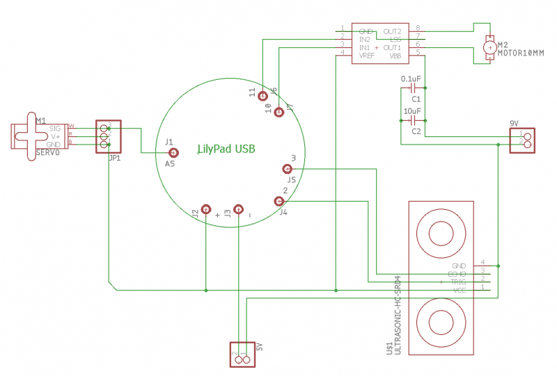
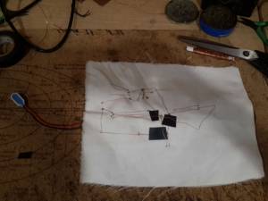
I was aware that for my final project I would propably use a servo motor for moving some flaps a and a DC motor for creating thrust for moving my project through the air. So I decided to add them to my circuit and for controlling them, I thought on an ultrasonic sensor. For controlling the DC motor I needed a motor driver, for changing the 5 volt signals to 12 volt, while for the servo I did not need any driver but a pwm signal; so for processing ad sending the signals to the motors I needed a microcontroller, in this case I chose a lilypad USB board which has a microcontroller atmega328p in it. The circuit I had In mind was the following.
The capacitors connected in parallel to the 9 V source in the circuit are for eliminating high and low frequency noise and are recomended to be used with the 4953 motor driver.
Sewing The Circuit
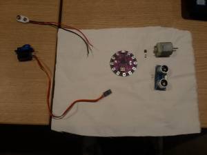
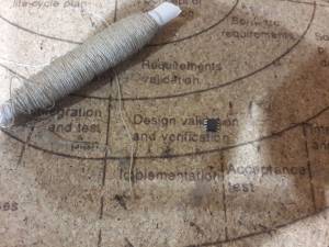
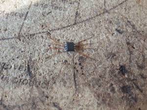
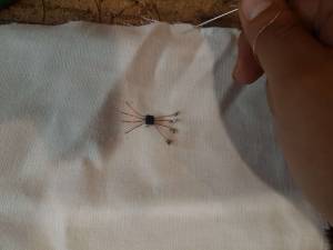
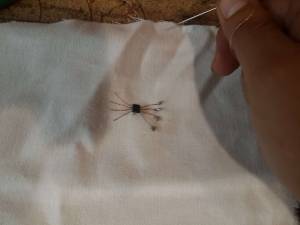
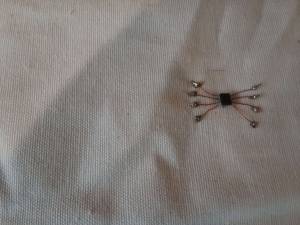
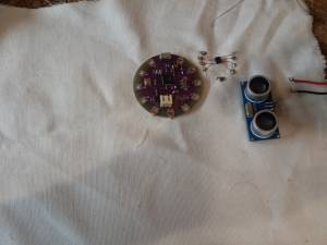
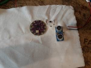
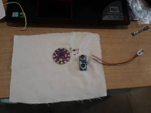
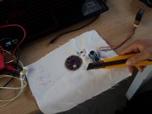
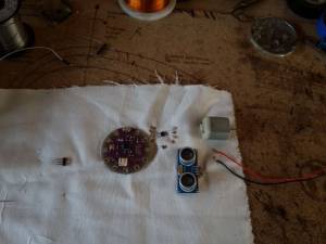
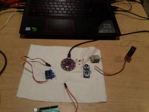
The first thing I did was to sew thee motor driver since it was the component that had the pads closer. At a begining I tried to soldered it directly to the conductive thread, but I realizad that it was almost impossible. So to solve this I soldered the pins to copper wire and expanded them, so that the component look like an spider, and then I fixed it to the fabric with conductive thread. Once I did this I started to sew all the components to the fabric and between them. Since the copper wire I used was very brittle, I sewed very carefully directly to the terminals of the components, that way I avoided that the fabric stretched too much so that it broke the copper wire.
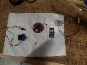
At a certain point I tried to test my circuit in the PC but I realized that the LyliPad had problems so I had to cut the wires that fixed the lilypad to the fabric changed it by one that worked correctly and soldered the remaining wires to it. Then I proceed to sew and solder the rest of the components and sewed the motor to the fabric with a common thread, this last action will move the fabric when the motor stops or changes it direction of spin, similar to when a car brakes suddenly and makes the passengers move.
Programming the Circuit
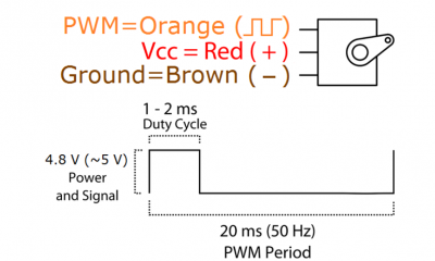
Luckily, arduino had already libraries to control the servo motor, so I did not had to create a function to control it. But just to explain it, the servo motor is actually compound of a DC motor which is controlled by a control circuit that reads the angle of twist of the motor with a variable resistance. This three components are packed inside the servo motor. And the signal that the servomotor needs is a PWM signal with a period of 20 ms of pulse separation (50 Hz) and an specific width for the pulse, between 1.5 ms to 2 ms. This last one indicates to the servo motor at which angle its axis should be rotated.
While the DC motor does not need any special function.So for controling the DC motor It is just needed that a currrent passes from one of its terminals to the other and the direction of this current determines the direction of twist of the motor. The arduino is connected to the motor driver, which is an H-Bridge that only changes the 5 volt inputs to 12 volt outputs, by its pins 10 and 11 instead of the dc motor. So for controlling the DC motor I just needed to set the pins 10 and 11 as follows: 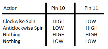
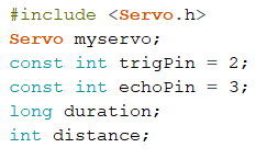
With this information, I proceeded to code. The first thing I did was to call the servo.h library and create a object of the class Servo. And then I declared the variables that I was going to use on the program.
Then on then on the setup block I defined the outputs and inputs of the LyliPad, I setted to Low the pins 10 and 11 that controls the DC motor, I defined the output pin that was going to be used by the Servo object and I iniitalizaed the serial communication with 9600 of baud rate. 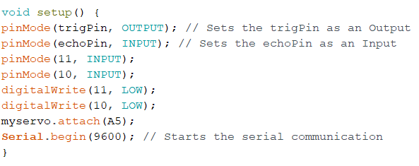
Then on the loop block, I create a pulse of 10 miliseconds on the trigger pin, so that the ultrasound sensor emits that pulse; after that, I called to the pulseIn function which waits until it recieves a signal on the echopin (that means that the sound wave have returned to the ultrasound sensor) and returns the time it passed until the signal was recieved; then, I calculated the distance of an object close to the ultrasound sensor by using the speed of the sound and the value of the time passed. Finally, I mapped the distance to an angle from 0 to 180 degrees and ordered the servo to move to that angle position with the function write.
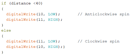
For the DC motor I just wrote a short code that changed the direction of rotation of the motor if the distance readen was greter or lower than 40 cm.
This is the result:
We can see that the DC motor makes the fabric move when it changes its spin direction, this is cause because of the conservation of angular momentum.
