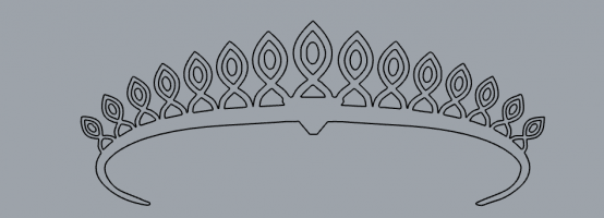
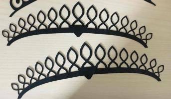
ASSIGNMENT
Use one of the project’s option (carnival masks or tech nails).
Personalize it with your project: change/add electronics
Improve the design: change the colors, add some crystals or other 3D elements.
Presentation: explain your motivation and how you personalized your project .
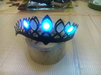
INSPIRATION: THE CROWN
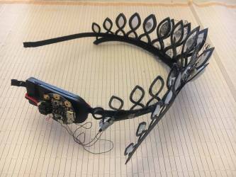
I don’t like wear things in my skin because it is very sensitive, so I decided to make my own DIY crown.
 | 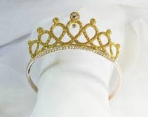 |  | 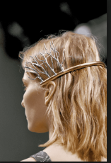 |
STEP 1: PLAN IT
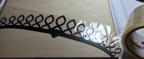
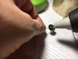
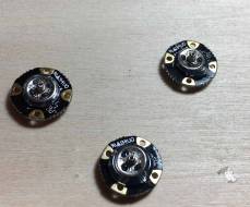
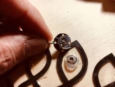
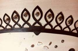
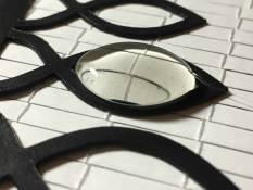
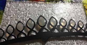
STEP 2: MAKE THE CROWN
 |  |  |
 |  |  |  |
.
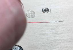
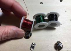
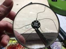
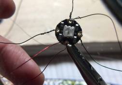
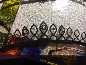
STEP 3: THE CIRCUIT
 |  |  |  |
 | 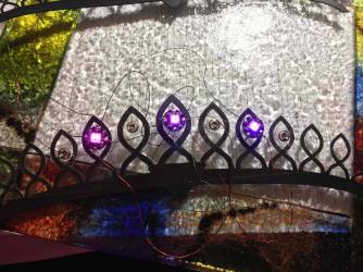 | 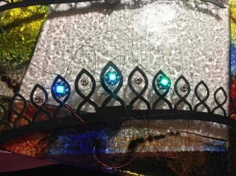 |
STEP 4: THE CODE
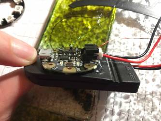
STEP 5: ASSEMBLY
 |  |  |


The Electronics
Our Board is Gemma V2
Half of the pads on the Gemma are related to power in and out: 3Vo , Vout and GND
- Vout - This is a voltage OUTPUT pin, it will be connected to either the USB power or the battery input, whichever has the higher voltage. This output does not connect to the regulator so you can draw as much current as your USB port / Battery can provide (in general, thats about 500mA)
- 3Vo - This is the 3.3V OUTPUT pad from the voltage regulator. It can provide up to 150mA at a steady 3.3V. Good for sensors or small LEDs or other 3V devices.
- GND is the common ground pin, used for logic and power. It is connected to the USB ground and the power regulator, etc. This is the pin you'll want to use for any and all ground connections

Arduino IDE Setup
I installed the Gemma Board following these steps in the Adafruit Arduino IDE setup guide to easily install a pre-configured Arduino IDE to program Gemma!
Blink!
After the instalation, is very useful to upload the blink code to the board and see that your PC is talking to your board. I followed this tutorial from Adafruit
And whe it all was done, I uploaded the code for the 3 neopixels. The code is available here
#include <Adafruit_NeoPixel.h>

#define NUM_LEDS 3 // Number of NeoPixels: 3 in my case

#define PIN 1 // DIGITAL pin # where NeoPixels are connected // IMPORTANT: Avoid connecting on a live circuit...

// if you must, connect GND first.

Adafruit_NeoPixel strip = Adafruit_NeoPixel(NUM_LEDS, PIN);

void setup() {
strip.begin();
strip.setBrightness(50); // 100/255 brightness (about 40%) strip.show(); // Initialize all pixels to 'off'
}
void loop() {
for(int j=0; j<256; j++) {
for(int i=0; i<NUM_LEDS; i++) { strip.setPixelColor(i, Wheel((i * 8 + j) & 255));
    }
    strip.show();
    delay(40);
}
}

// Input a value 0 to 255 to get a color value.
// The colours are a transition r - g - b - back to r.
uint32_t Wheel(byte WheelPos) {
if(WheelPos <85) {
return strip.Color(WheelPos * 3, 255 - WheelPos * 3, 0);
} else if(WheelPos <170) {
WheelPos -= 85;
return strip.Color(255 - WheelPos * 3, 0, WheelPos * 3);
} else {
WheelPos -= 170;
return strip.Color(0, WheelPos * 3, 255 - WheelPos * 3);
} }
