Open Source Hardware - From Fibers to fabric
INTRO
This week assignment was about hacking or creating a new machine related to the world of textiles (fabrics, threads, fibers, knitting, etc) .
Our choice was to use the CNC Milling Machine to take advantage of the movements X ; Y ; Z already existing , the size and the software to make a big embroidery machine.

To get the embroidery, we decided to use a Punch needle (or “magic” needle) which does not need any thread underneath . A simple use of a spool is enough for a hand job .


For the transformation of the Milling Machine, it is necessary to create a tensor with a spool holder for the thread, a needle adapter and a frame to hold the fabric .
I/ Needle Adapter
(Sofia part)
The adapter has been designed to attach the needle to the CNC nozzle.
Characteristics:
- Adaptable for 1 o more needles.
- Removable.
- Easy to change the needle and adjust the length of the point.
- Doesn't interfere with the functioning of the machine
- Light weight

Holding needle structure with an adjustable clip to hang on the machine.
Step 1 :
Learn how to use the needle. A few test with different threads and fabric have been done :
- Tulle
- Calico
- Cotton twill
For loose knitted fabric it works better with a thicker thread.
Step 2 :
Measurements were taken from the machine (noozle and bit holder), so we could design the piece on Rhino.
Step 3 :
3D modeling in Rhino and printing.
Step 4 :
Printing and first tests.


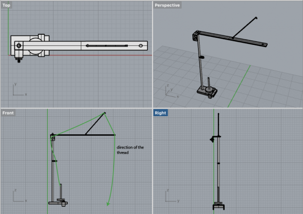
II/ Tensor Mechanism
(Fanny and Pauline parts)
The tensor is used to adjust the thread tension caused by the needle.
We decided to make a handmade tensor with metal stick / bar / thread and tensor tools with a spool support to put on the CNC milling machine.
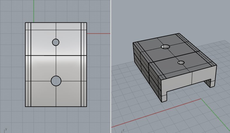
The part of the milling machine chosen for the tensor.
This part of the machine has a space to put a base and also has already a hole to screw something on.

The measurements have been taken to create a structure.

1) The Base
The idea was to have a piece with legs to grap the metal part of the machine and make it stable. We did a hole of 8mm (the diameter of the one on the machine) and one of 6mm to add a stick for the spool.
Issue :
We used the milling machine to do the 3D structure but we we encountered some problems.
The bit of the machine didn't mill the surface by layer but was going directly into the wood more than 10mm deep making an unusual noise.

So we decided to cut a piece of wood and add a metal structure around to keep it stable.

The wood wasn't gripped properly so we add some foam tape inside.


2) Spool
On the piece of wood, we add a hole as explained before to inlay a wooden stick.

We added a support underneath to sustain the spool.
3) Tensor Tools
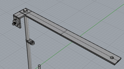
a. Metal Bar
We bought a 8mm diameter metal stick to fit in the hole.
A perpendicular metal bar has been screwed on top of the stick like a crane.
To have the possibility to add the tension dial we bent the metal bar.

Bended metal bar for the tensor.
_

_
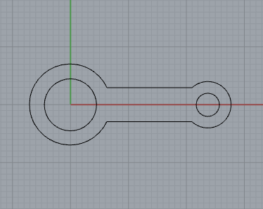
b. "Holder Thread" Piece
Used to direct the spool thread to the tension tool. Is placed on the metal stick.
We laserCut the piece in Plexiglass.

In three different size to test.

- 8mm ( the diameter of the stick) too big, with the heat of the laser the plastic melts.

The piece goes down and does not stay in place.
- 7mm the plastic is to tight and does not pass.
- 7.5mm is the right measurement

_
c. Tension Wheel.
Serves to decrease or increase the tension of the thread.
Tools :
- A Screw
- A Spring
- Two metal discs, one curved to make the setting of the thread easy.
- A Bolt for resistance on the other side.
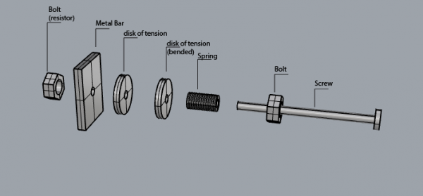

Once the tension Tool on the bar, we realized that the thread coming from below and passing through the tension dial could not followed the right direction so to be on the orientation of the metal bar.

We decided to cut the metal in two part and put the pieces one over the other with a screw, crossing each other.
_
d. Tension Metal Thread.
Use of a metal rod shape memory as it serves to dampen the tension of the thread.
Torsion of the ends of the stem, a loop to fix it to the bar and the other to pass the thread. It has to be perpendicular to the metal bar to keep the motion in the axis.

Movement of the rod, up and down.

To fix it, two holes in the metal bar and a twisted wire.
We had to sold the wire to the rod because it was not strong enough.

The loop of the rod must be in aligment with the metal bar hole to prevent the thread from wearing on the rim.
III/ Frame
Idea :
Create a framework to stabilize the fabric.
Two wooden bars held by four blocks with cranks to stretch the fabric on each side.
1) research idea and draw of the file
(Brigitte and Julia part - link will follow)
Drawing on illustrator of the blocks part with a central hole for the wooden bar surrounded by small holes that will be used to lock the handle by inserting nails.
2) Blocks and crank
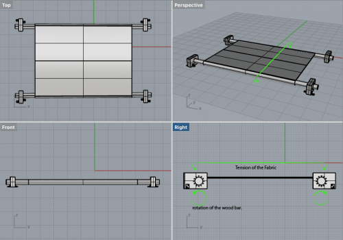
Preparation:
- Hole the wooden bars on each side to put metal bars that will act as a handle.
- laser cut the file

_


- Assembled the layers with glue for wood. was left to dry overnight in a press.
- Screwed the “L” to the blocks (to attach them to the base of the milling machine.)

Assembly:
- stapled the fabric to the wooden bars.
- Inserted the wooden bars in the blocks.
- Added metal rods and closed with a bolt.

- Nailed the blocks to the base table of milling machine.

IV/ Test
As a starting point, we designed very simple paths, to see how the machine was reacting to the basic orders.
Path 1 : Distance between the points

We created a line with a few points, and decreased gradually the distance between the points :
- 20mm
- 15mm
- 10mm
- 5mm
- 2mm
The aim of this test was to see which kind a distance was giving the best visual result.
We tried different settings because the thread was not staying in the fabric.
The speed, deepness and tension of the fabric were not enough for the needle to go properly through.

To mesure the Z axe :
- Automatically : Place the end of the embroidery needle and the end of the bit of the machine in the same level. Use the metal captor and place it on the origin : here on top of the fabric (you can use a support underneath so the fabric doesn't bend)
")
- Manually : Place the needle on top of the fabric and set “0 axe” on the height you choosed.

Then unscrew the bit and turn off the part of the machine driving the rotation and turn the spindle speed to 1 (the machine doesn't accept 0), so that you are sure to use the machine in a safe way.


 .
.
Path 2 : Single curve

Path 3 : Random points
Path 4 : Curvy polyline
Path 5 : Polyline with angles
V/ Final view of the Embroidery Machine

Perspective
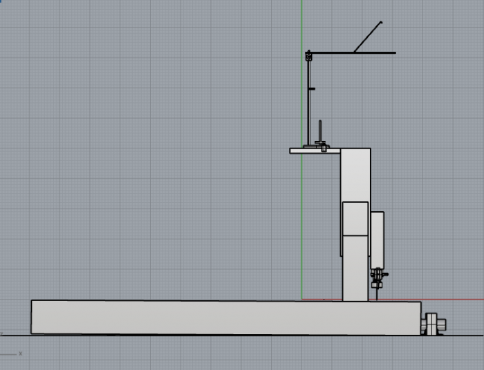
Side view

