Look at the tutorial for laser cutting
1. IDEAS
This was the most important part for me, I think, because it was the only part that required thoughtful thinking, and afterwards the whole process became a lot more centered and focused. Having a vision in my head helped me understand what I wanted, and therfore I directed my questions and attention to that. I understand that not for all assignments I can be very soecific, because interesting findings can make me deviate, but for a simple task where I sort of understood what I had to do to make that happen, it definetely helped.
2. SCAN
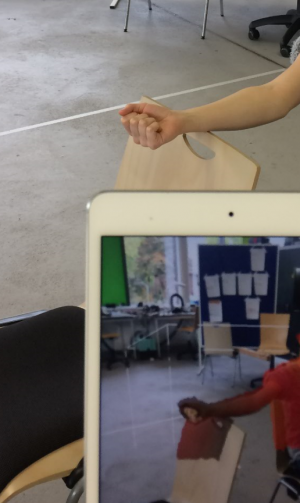
Here, I find out the perfectionist if the first step was very important, then this step was vital to have a good start for all the future steps Without putting too much pressure, this is the step which would make your life a lot easier for the rest of the steps. I made maybe 7 scans in total, to the discomfort of my classmate, in (whom I thank profusely) in order to make the ethe most complete scan of my leg, which has many complications. To begin with, one needs to remain still, and the scanner must be able to move around it, without getting too close, so as to make a full scan. Since my vision included my foot, I had to manoscritti myself in a modeling position, where the leg was raised on the edge of a chair. From experience I had scanning my classmates, it was vital to have right or removal clothing.
3. EDIT
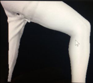
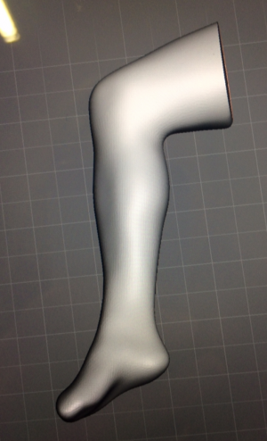
This part I had plenty of experience with, since I did it a couple of times, with different scans of my legs. Here is where I learnt to make a great scan, because even if it is possible to sculpt and edit and fill and remove parts in MeshMaker, it often took more effort than doing another scan. I think it’s important to play around with the toolbox, but having the basic four commands (plane cut, remove, fill and make solid) was enough. It was vital that smooth was implemented at the end, as well as the tool , called readijst, to then export it (dsx) and into another software, and make the object more simple and more pixelated, so it can afterwards move faster. For body parts, the quality was definitely more than enough, but if one were to do have more details, with zoom, in the editing part it is important to emphasize it
4. PUT ON SLICER
Slicer is an add-in of Fusion 360, which is very compatible with the laser cutter, since one is able to modify the material and size of the material the laser cutter will have, as well as edit the form of the object (stacked, interpacked…).
The number of sheets is then calculated. The sheets are then exported via obj (or stl)
5. OPTIMISE MATERIAL USE
Using Rhino, (Illustrator could be an alternative, but the sheets have to be copied and pasted in a new document to import all of the pages if you have more than one) I was able to import the sheets, one by one, to the workspace.
Since I had 11 sheets, to optimize material usage, I narrowed it down to 6. Here is how I did it: I grouped each figurine together(control-G), so it was easier for me to move them around and “play” with the space placed of each one. And then I used the rotate, mirror and mouse to move around each figurine, until I was happy with the amount of sheets used.

6. PRINT TO THE LASER CUTTER
Joining the dots together made the laser cutter’s time decrease by 10-fold, in my case.
I then clicked print and formatted the sheets I wanted (deleting the borders) horizontally, in order to place the white box. The white box showed me what I would print.

To calibrate the machine, look below.
6a)Settings
Here, calibration is required, and so the color sensitivity is switched on, and the speed, power and frequency is adjusted for each color used, and prioritized in base on what I want the computer to look at first. The colors not on the sheet of paper can be left alone. The lighter the color, the less the cut will be. For example, red was used to number and outline the parts, and blue was used to cut the figurines.
6b)Try
It is necessary that for the first sheet, a shape is added (using the main menu, and located where there are no parts that will be cut) and all the other parts are hidden using the lightbulb configuration.
6c)Repeat until satisfied
The latter is tried until one is satisfied with the result, that the cut is fine.
6d) Print
This done until all the sheets are printed. There is no need to continuously calibrate the machine for each sheet, just make sure to RESET (by pressing the reset button on the laser cutter) after each sheet is printed, so that the laser cutter knows to receive another dataset from the computer.
7. PASTE PARTS TOGETHER
This is the part that I rushed, since I was a perfectionist with everything else, but predicted that this part would be easy. It is vital to align each part so that they all seem purposely put this way.
Either ways, I was satisfied with my result, and am thrilled that I learned a new skill, especially because I now know the basics of how to operate a laser cutter.


To configure and calibrate the laser cutter:
Make sure the ventilation tube is placed outside, and it is turned on. Depending on the size of the material, one may need to adjust the ventilation screens inside of the machine.
REMEMBER: to open the lid, the machine must be in focus
- To calibrate the material and the laser’s distance, a top is adjusted on the laser’s parts, and the joystick is used to move the parts until the point f the calibration tip is even with the material. This is done in the job setting by pressing the corresponding button. To make sure this is true, the tip is moved and there should be no drag, since it is loose, it should remain straight.
- Press the light button and a red light will appear where the laser will cut. Adjust this to the origin (0,0) point, using your eye.
Fusion 360 is commonly used to put parts together, and creat new shapes and figures to be printed later. This program is very useful, but has a language of its own. Unfortunately, I didn’t make use of it this time (only the Slicer plug in) but I am sure that I will in another project, since it seems very useful
CNC (control numerical control) milling
This is used as subtractive manufacturing process, where the object is carved out of the material, using a grinding tip, or more specifically, the floss of the tip.
This machine uses coordinate system, and has axis that go in three directions.
Length and thickness must be considered since the end mills (points of the carving tool) are only a certain length.
A limitation is that the corners must be designed for allowance, if one wanted to press a shape into another