TALKING ARPILLERAS

PROJECT
“Talking Arpilleras” is a project that explores how the integration of new technologies can add value to a traditional textile technique, by adding new layers of information that enhance its main communicative effort.

1. STUDY OF ELECTRONICS
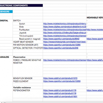
Understanding of components: The first thing I did was to make a list of all the components I thought I will use and organize them into categories according to microcontroller, sensors, actuators, accessories and power. Also, I search for traditional ones and soft and DIY versions. All this info is here
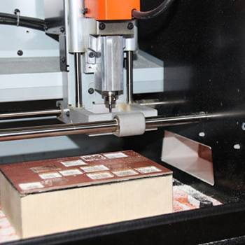
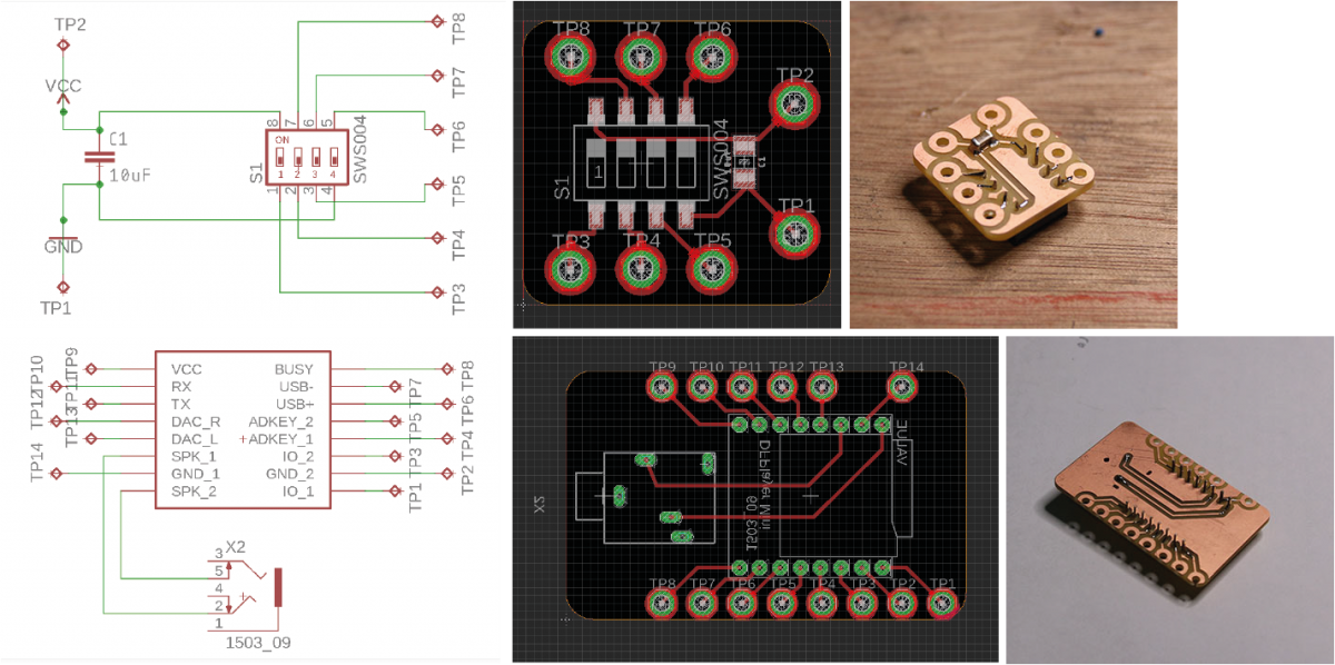
PCB: I learn how to design PCB`s with Eagle and to cut them with a Roland CNC milling machine. Also, how to solder the components.
Definition of the materials: I made a list and bought them online (Aliexpress). I decide not to use any of the Lilypad or Flora components because they were expensive and I wanted to make my own ones.


2. LEARNING ABOUT ARPILLERAS
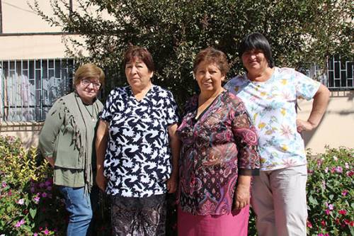
Meet the artisans: I reach a recognized group of Arpillera Artisans and ask if they wanted to work with me. I made some samples to show and explain the idea, trying to be the most transparent I could about the goals and objectives. They are from the city Melipilla, near Santiago (Chile). Is a group of 7 women that work together since the 80`s and they sell their pieces at fairs. I mainly worked with Maria, Telva, Magdalena, Gladys and Adriana. From the beginning they were super excited to try this new “experiment” because they saw it as an opportunity to make the Arpilleras become even more “alive” and to learn new things.
Learn about the technique: This technique was born in the 70`s to help women to gain money by doing a really simple textile technique and also as a way of protest against Pinochet`s dictatorship. So, from the beginning, this technique wanted to tell stories using recycle fabrics put together with embroidery stitches. Now, they don`t longer tell stories about the dictatorship but about the life of people from the country side of Chile. They want to show and share the lives, animals and landscapes of Chile in a beautiful way.
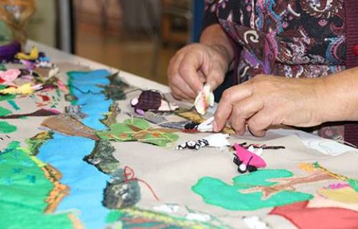
Experience the technique: The artisans gave me a class about how to make arpilleras, so I learn about the design process, the fabrication steps and the main stitches.

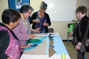
3. WORKSHOP FOR CO-CREATION
Planing of the workshops: After the class they gave me and asking them about their times, I plan a list of work sessions to co-design and create the piece together. Because it wasn't a job I was going to do alone, I needed to really thing about the steps. To do this, I thought about a system of layers that help me construct the piece and add the electronics in a logic way. In total, I planed 6 sessions, divided intro design and fabrication.
Material for the workshops: For the design face, I create a list of the sensors and actuators I wanted to use and make a “kit” of icons that I print and cut on paper. This kit help me design the piece with the artisans adding this new information about electronics.


Co-Design of the piece: The first session of the workshop was about the design of the piece. So, first we decide together how was the story we wanted to tell with the Arpillera. The decided to show the life of working people living in the fields of the center of Chile and the characteristics landscapes of the region. So, the main images of the Arpillera are the Andes Mountains, fruit trees, typical animals like horses, cows and chickens, and working women and men making wool, cooking and looking at the animals. Then, with the kit we decided what information we wanted to add, like sounds, movement, lights, ect. The piece is about 1000 x 700 mm.


4. CREATION OF THE ARPILLERA
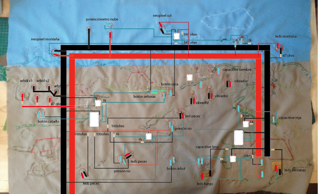
1. Mapping of the components: With the design clear and all the pieces of fabric cut and ready and attach with big stitches, I took the piece home and start working with the sensors and actuators. To do the mapping of where was everything, I took a picture and put it on Adobe Illustrator to trace the fabric drawings and add the info about the sensors, actuators and microcontrollers.

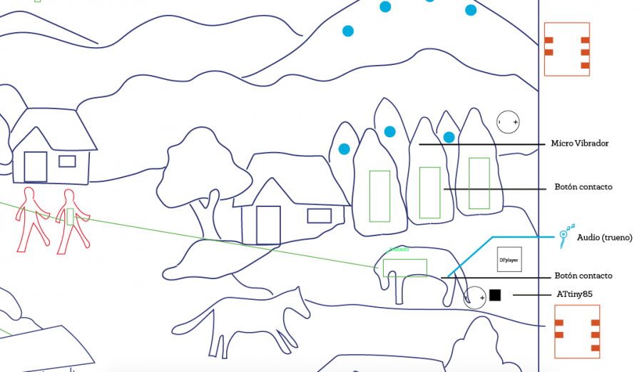

Schematic:

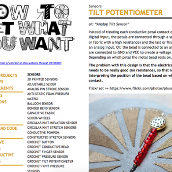
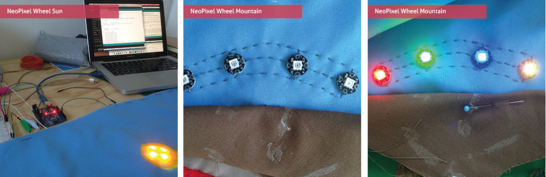
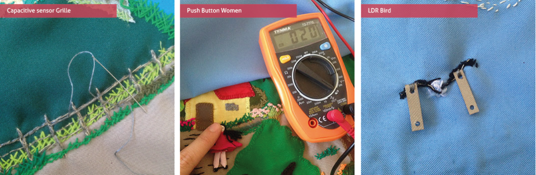
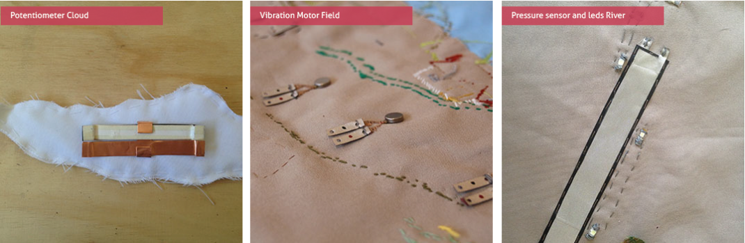
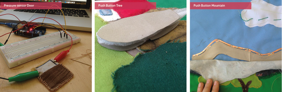
2. Samples of components: Once I knew the components I was going yo use, I started doing samples of the soft version of each one. For example, learn how to make a pressure sensor with velostat and a capacitive sensor with conductive fabric. After the samples where working and try them all with the coding in Arduino, I started adding them to the Arpillera. In the all process the main steps were: learn how to use the traditional component and the coding using Arduino, then translating the coding to ATtiny and check and finally make the soft-version of the component and try it with the coding.
Here are some of the links I visit to learn about the components:


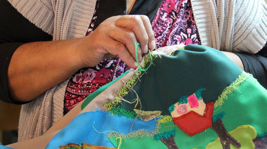
3. Embroidery: While I was working on the samples, I took the piece back to the artisans, so they could start with the embroidery of the pieces that didn`t have any component hidden inside.

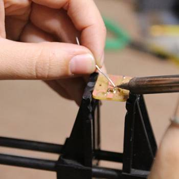
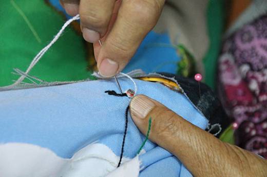
4. Integration of components into the fabric: One important thing I needed to figure out was how to make the connections of the components to the main traces of the circuit. I decided then to create small taps made from two layers of conductive fabric and paint them with a small drop of nail polish with 3 different colors: black fro GND, red for VCC and blue for the PIN. For the isolation of the tread I also use transparent nail polish. The nail polish is a really good material because it doesn`t faint and is easy to apply. The all time I was working in this, I use the multimeter to check all the connections.
Materials and equipment:
- Needles
- Embroidery scissors
- Multimeter
- Bench power supply
- Soldering iron
- Batteries
- Arduino board
- Protoboard
- Jumper Wires
- ATtiny 85
- Adafruit Conductive Tread
- Conductive fabric
- Resistances
- Transistor 2N2222
- Vibration motor
- DFPlayer MIni
- Jack adapter
- 8w speaker
- High power leds
- NeoPixels
- Velostat
- LDR
- Foam
- Copper tape

5. Final embroidery: With all the hidden components already integrated into the fabric, I took back the Arpillera to the Artisans and we finish all the embroidery before adding the back circuit.
6. Creation of PCB: I decided to use ATtiny`s instead of Lilypad because they are cheaper and also I could distribute them better around the big piece of fabric, to avoid having too long traces of fabric that could add to much resistance to the circuit. So, I create my own pcb to add the microcontroller, with a smd 10 uf capacitor and holes be able to sew it to the fabric. For this, I learn to use Eagle for the design, Mods and the Roland CNC milling machine to cut the pieces of plastic/copper. I also made a pcb to add the DFPlayer mini and the jack adapter. You can find the files here
7. Fabric mask for the traces of the circuit: To create the circuit and connect all the components, I create a fabric “mask” where I could sew all the traces and be independent of the Arpillera embroidery. For this, I took a top view picture of the back of the Arpillera, and create a dxf file to laser cut fabric but leaving the specific holes so the taps could go trough and then be connected to the circuit.


8. Sewing the circuit: With the fabric mask in place, and the schematic, I create all the paths for the traces. The main traces are VCC and GND, and I made them with conductive fabric that I sew with a sewing machine. For the connections of the pins I use conductive tread that I hand embroidered. I already knew that this materials (both the tread and the fabric) even if they are conductive, have resistance that increases with the length. In the case of the thread, I use the multimeter to check and it looses the conductivity around the 70 cm so I was checking to not make traces longer than this. In the case of the trace made with fabric, from the start until the end, has 90 ohm of resistance.


Coding
1. Capacitive sensor + Vibrating motors
#include <CapacitiveSensor.h>
CapacitiveSensor cs_3_4 = CapacitiveSensor(3,4); 10M resistor between pins 4 & 2, pin 2 is sensor pin, add a wire and or foil if desired
int Motor1 = 2;
int Motor2 = 1;
int Motor3 = 0; void setup()
{
pinMode (Motor1, OUTPUT);
pinMode (Motor2, OUTPUT);
pinMode (Motor3, OUTPUT);
cs_3_4.set_CS_AutocaL_Millis(0xFFFFFFFF);
} void loop()
{
long start = millis();
long total1 = cs_3_4.capacitiveSensor(30); if (total1 > 5000) {
digitalWrite(Motor1, HIGH);
digitalWrite(Motor2, HIGH);
digitalWrite(Motor3, HIGH); }
else{
digitalWrite(Motor1, LOW);
digitalWrite(Motor2, LOW);
digitalWrite(Motor3, LOW);
}
}
2. Flex sensor + Leds
int sensorPin1 = 3;
int ledPin1 = 0;
int ledPin2 = 1;
int sensorValue1 = 0; void setup() {
pinMode(sensorPin1, INPUT_PULLUP);
pinMode(ledPin1, OUTPUT);
pinMode(ledPin2, OUTPUT);
} void loop() {
sensorValue1 = analogRead(sensorPin1);
delay(100);
if(sensorValue1 < 350){
digitalWrite(ledPin1, HIGH);
digitalWrite(ledPin2, HIGH);
}
else{
digitalWrite(ledPin1, LOW);
digitalWrite(ledPin2, LOW);
}
}
3. Pressure sensor + leds
int sensorPin1 = 4;
int sensorPin2 = 3;
int ledPin1 = 0;
int ledPin2 = 1;
int ledPin3 = 2;
int sensorValue1 = 0;
int sensorValue2 = 0; void setup() {
pinMode(sensorPin1, INPUT_PULLUP);
pinMode(sensorPin2, INPUT_PULLUP);
pinMode(ledPin1, OUTPUT);
pinMode(ledPin2, OUTPUT);
pinMode(ledPin3, OUTPUT);
} void loop() {
sensorValue2 = analogRead(sensorPin2);
delay(100);
if(sensorValue2 > 580){
digitalWrite(ledPin3, HIGH);
digitalWrite(ledPin2, HIGH);
digitalWrite(ledPin3, HIGH);
}
else{
digitalWrite(ledPin3, LOW);
digitalWrite(ledPin2, LOW);
digitalWrite(ledPin1, LOW);
}
}
4. Light sensor + Neopixel wheel
#include <Adafruit_NeoPixel.h> #define PIN 7 Which pin the pixels are connected to
#define LED_COUNT 8 Number of pixels used
int sensorLuz = 0;
int sensor_value = 0; Adafruit_NeoPixel leds = Adafruit_NeoPixel(LED_COUNT, PIN, NEO_GRB + NEO_KHZ800); void setup()
{
leds.begin(); Start up the LED strip
leds.show(); LEDs don't actually update until you call this function
pinMode (sensorLuz, INPUT);
} void loop(){
sensor_value = analogRead (sensorLuz);
delay(100);
if (sensor_value > 300) {
leds.setPixelColor(0, 0, 0, 0);
leds.setPixelColor(1, 0, 0, 0);
leds.setPixelColor(2, 0, 0, 0);
leds.setPixelColor(3, 0, 0, 0);
leds.setPixelColor(4, 0, 0, 0);
leds.setPixelColor(5, 0, 0, 0);
leds.setPixelColor(6, 0, 0, 0);
leds.setPixelColor(7, 0, 0, 0);
leds.show(); Display the colors
} if (sensor_value > 150 && sensor_value < 200) {
leds.setPixelColor(0, 255, 255, 0); AMARILLO
leds.setPixelColor(1, 0, 0, 0); NARANJO
leds.setPixelColor(2, 255, 255, 0); AMARILLO
leds.setPixelColor(3, 0, 0, 0); NARANJO
leds.setPixelColor(4, 255, 255, 0); AMARILLO
leds.setPixelColor(5, 0, 0, 0); NARANJO
leds.setPixelColor(6, 255, 255, 0); AMARILLO
leds.setPixelColor(7, 0, 0, 0); NARANJO
leds.show(); Display the colors
} if ( sensor_value < 150 ) {
leds.setPixelColor(0, 255, 100, 0); AMARILLO
leds.setPixelColor(1, 255, 100, 0); NARANJO
leds.setPixelColor(2, 255, 255, 0); AMARILLO
leds.setPixelColor(3, 255, 100, 0); NARANJO
leds.setPixelColor(4, 255, 255, 0); AMARILLO
leds.setPixelColor(5, 255, 100, 0); NARANJO
leds.setPixelColor(6, 255, 255, 0); AMARILLO
leds.setPixelColor(7, 255, 100, 0); NARANJO
leds.show(); Display the colors
}
}
5. Capacitive sensor + MP3 Player
#include “Arduino.h”
#include “SoftwareSerial.h”
#include “DFRobotDFPlayerMini.h”
#define ACTIVATED LOW
#include <CapacitiveSensor.h>
#define TOUCH_CAP 10000
#define PLAY_TIME 4000
Objetos
SoftwareSerial mySerial(10, 11);
DFRobotDFPlayerMini myDFPlayer;
CapacitiveSensor cs_4_2 = CapacitiveSensor(4,2);
const int buttonPlay3 = 3;
bool button_play = false;
bool cap_play = false;
long cap_play_start = 0;
long button_play_start = 0;
()
{
cs_4_2.set_CS_AutocaL_Millis(0xFFFFFFFF);
pinMode(buttonPlay3, INPUT);
digitalWrite(buttonPlay3,HIGH);
mySerial.begin (9600);
Serial.begin (115200);
{
Serial.println(F(“Unable to begin:”));
Serial.println(F(“1.Please recheck the connection!”));
Serial.println(F(“2.Please insert the SD card!”));
while(true);
} Serial.println(F(“DFPlayer Mini online.”));
myDFPlayer.setTimeOut(500); Set serial communictaion time out 500ms delay(2000);
} void loop ()
{
long total1 = cs_4_2.capacitiveSensor(30);
Serial.println(total1);
Serial.println(“\t”);
delay (100);
if(total1 > TOUCH_CAP)
{
if (!cap_play || (millis() - cap_play_start) > PLAY_TIME)
{
myDFPlayer.play(1);
cap_play = true;
button_play = false;
cap_play_start = millis();
}
} if (digitalRead(buttonPlay3) == ACTIVATED)
{
play3();
if (!button_play || (millis() - button_play_start) > PLAY_TIME)
{
myDFPlayer.play(3);
cap_play = false;
button_play_start = millis();
}
}
}