Documentation 25.10.2017
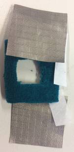
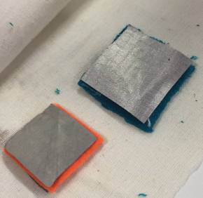
Today we worked on the first assignment with the LED circuits. Therefore, we built a sensor looking like a sandwich. The sensor consists of two conductive fibers and in the middle a non-conductive one. As the conductive fiber I used Shieldex Nora Dell with 1 Ω of resistance and a non-conductive fabric. Very important for creating a sensor is that the non-conductive piece is bigger than the conductive ones, so it prevents any contact of the conductive fibers with each other.
To fix the parts of the sensor to each other, we used “Bügelfix”, which is something like a glue, and an iron to make the glue melt and fixing the parts.
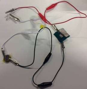
After receiving the sensor, we built the circuit. For this, we used alligator clips, a 3V cell-coin battery and a LED. Now you connect every part to each other, but be careful - the order has to be correct!
You connect the anode of LED to the negative side of the battery. For this, you also have to isolate the positive side of the battery. Then you connect the cathode of the LED to the positive side of the battery and again isolate the other side of the battery, so in this case the negative one.
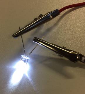
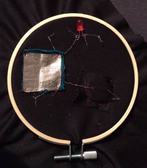
After successfully doing this, you prepare everything to put your circuit on textiles. For this, we use conductive thread, a battery bag, which you should do before, the LED, the cell-coin-battery and a piece of fabric, we worked with linen. After preparing, we began sewing every part of the circuit onto the linen. Finishing this, you only have to press the sensor and the LED lights up.
Unfortunately, this did not work for me because I had many short circuits on my textiles. These arised because I wanted to ensure that everything is fix, so I did many nodes.
Because of that I had to do it again and this time I just did simple connections. And it works fine! :)
 |  |  |
 |  |
Documentation 26.10.2017
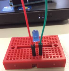
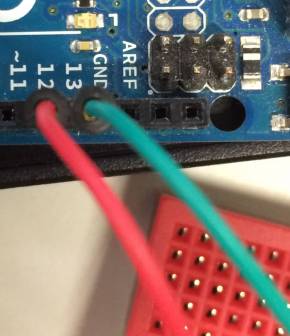
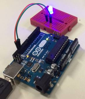
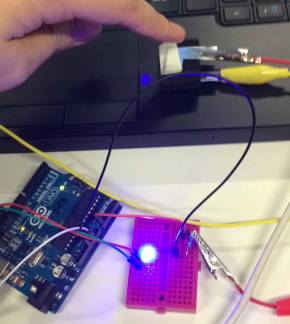
Today we met for an Arduino tutorial. Arduino in general is an open source platform that allows you to program with Arduino programming language. We brought our circuits onto breadboards and programmed them with Arduino. For bringing the circuit onto the breadboard, you first connect your LED, then two cables ( I chose a green cable for the negative connection and a red one for the positive connection), you connect the “positive cable” to port 13 on the Arduino board and the negative one to ground (GND on your Arduino board). The reason for connecting the “positive cable” to port 13 is that there is already a resistor installed. If you connect it to another port, you have to add a resistor manually.
Then we started to do our first code, which was to blink a LED with the Arduino programming software. To do this, you open the menu tab “file” and then “examples”, “basics” and choose “blink”. After this, you connect the Arduino board to the computer via a cable. Now you have to click on “verify” and “upgrading” and your LED will light up.
Then we created a new sensor because we want to do the same circuit we did yesterday again but now using Arduino. After connecting your circuit, you connect again the Arduino board to the computer and now you can click on “Serial Monitor” to see the different values. Using this code,the LED is lighting the whole time unless you press the sensor. Then it will turn off.
Very important for working with Arduino is that you do not connect the Arduino board while programming and you have to check your connections before connecting it to the computer. Because in worst case you can damage your computer.
 |  |  |  |