Aptus Sole - Technical Part
https://www.youtube.com/watch?v=Qn6W3ZsT7sc
Basic Idea - Sensor development
The Aptus sole is based on a simple input and output system. The input being the incorrect, over pronated gait and the output being the vibration. The input can be defined as the excessive inward rolling of the foot, therefore there will be an increase of pressure on the sensor of the base of the big toe.
Once the predetermined threshold of pressure has been detected by the pressure sensor the wearer will be alerted through the vibration feedback.
The sensor will be programmed using Arduino micro controlling. By using an “if statement” the program can evaluate the situation and give the vibration output if the pressure detected is over that of the predetermined threshold.
Work load sensor- Sensor development 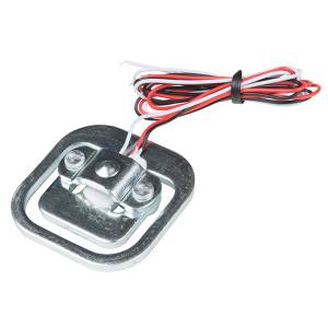
We used:
-Load Sensor- 50kg
-Load Cell Amplifier HX711
- Arduino
-https://learn.sparkfun.com/tutorials/load-cell-amplifier-hx711-breakout-hookup-guide?_ga=2.161400637.1024648294.1520424525-1842211797.1510845344
For our first try we decided to work with the Load Sensor- 50kg (SEN-10245) which is often used in scales. (For our purpose 50kg are more than enough cause you will never have your whole body weight on the pressure point we chose.)To get measurable data from the load cell we used the Load Cell Amplifier HX711(SEN-13879). Luckily for us there already exists a “Load Cell Amplifier HX711 Breakout Hookup Guide“. It already gives you a calibration code and a simple scale code for Arduino.
However, we were a little bit worried that the workload sensor is too “hard“ and will get to uncomfortable for a highly sensible body part like the foot because you will always will stand on it.
Our possible solution for this problem was to build a little pocket into the sole. So just the top of the Load sensor will be visible. 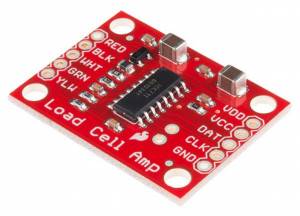
Nevertheless, we tried to use this instruction to hook up the Workload sensor and the Load Cell Amplifier with the Arduino.
(Tip: Check if all your equipment (alligator cables, jumper wires) are working. It will save you a lot of time and frustration ;))
It is a good instruction for connecting several Load sensors but unfortunately did not work for us. We wear not able to connect the Load Sensor & Load Cell Amplifier to the Arduino. Unfortunately, we are not quite sure why.
After several failed tries we decided to consider another direction.
DIY Pressure sensor - Sensor development
For this we used:
-Sensor Film Kit
-http://www.sensorfilmkit.com
- Polyethylene PE553 Foam
-Arduino
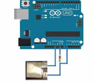
In wearables I, we created a kind of switch using conductive and semi conductive material. We decided to test this idea by using the Sensor Film Kit. It contains a black plastic sensor film (semi conductive), heavy aluminum foil (conductive) and clear adhesive polyester film. Again a big help was the already existing instruction.Using the example “AnaloginOutSerial“ code of Arduino I tried to detect a threshold. Because all materials are so close together the numbers of the serial monitor where quite high but the basic concept worked. We decided to build another sensor using semi conductive foam instead of the black plastic sensor film. This time the numbers were not that high and we decided to use it as a pressure sensor. Big advances of this sensor are its “softness“ which is way more comfortable for the wearer than the Load Sensor. Doing some “test standing“, showed us that you do not even feel it which is great.
 | 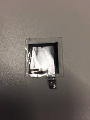 Test Sensor Test Sensor | 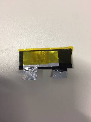 Final Sensor Final Sensor |
Connecting Pressure and Vibration Sensor - Sensor development
For this we used:
-LilyPad Vibe Board
-Selfmade Presser Sensor 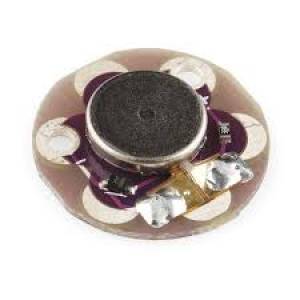
-15kΩ Resistor
-Arduino
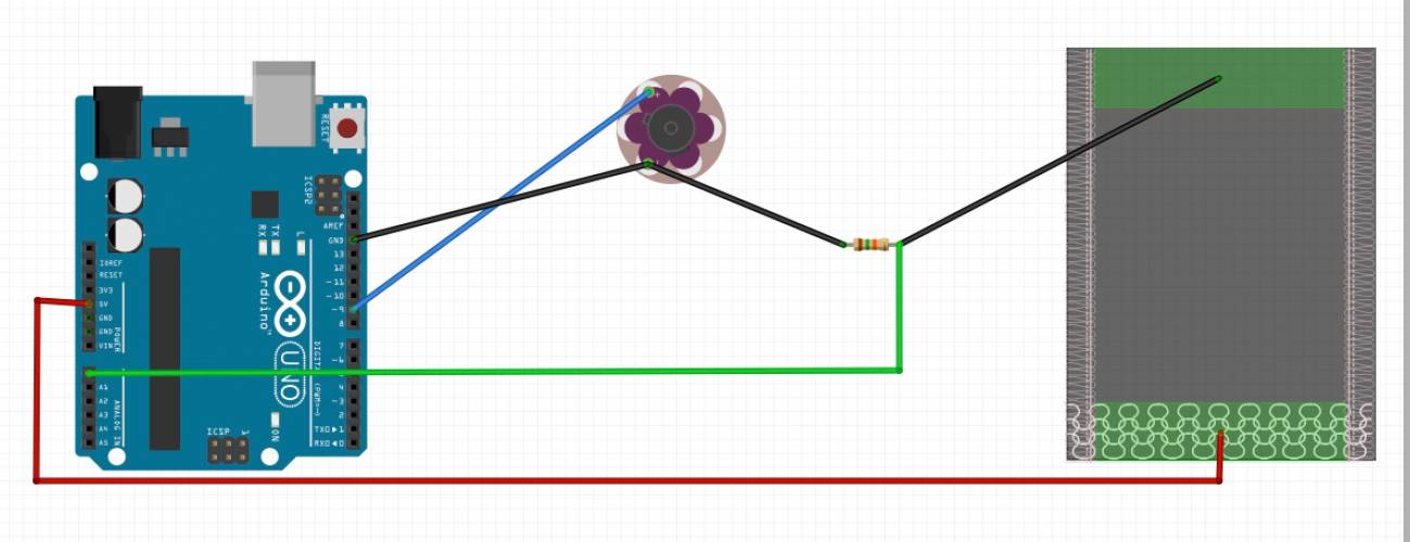
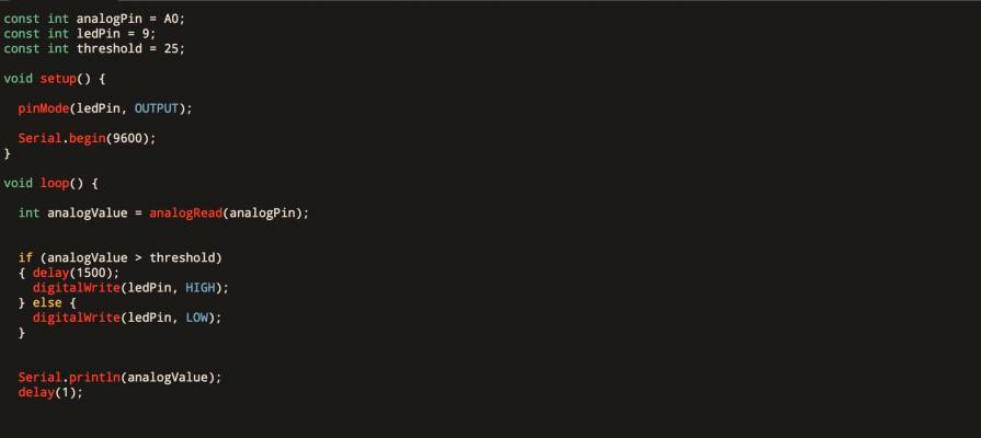
To evaluate the situation the program runs with an “If Statement“. Here we used the example code of Arduino which you can find under—> Examples —> Control —> IfStatementConditional. This code is intended for an LEDPin. But the LilyPad Vibe Board works exactly like an LED so it does not have any influence on the final result. Of course, we had to adjust our settings like Pins and threshold. We also included a 15kΩ resistor in the circuit to keep the output numbers of the serial monitor in a plausible range. The higher the resistor the smaller the numbers of the serial monitor. Generally speaking, our numbers were quite small. Besides that, we made another little time-delay adjustment in the code. The feedback sensor should not react to every little contact, that is why we decided to make a delay of 1.5 seconds. The LilyPad Vibe Board is only triggered if you stand on the pressure sensor with the predetermined threshold for more than 1,5 seconds.
pic of delay thing
 |
Determine the threshold and placement of LilyPad Vibe Board - Sensor development
The pressure threshold of the wearer has to be determined. We figured out the perfect threshold by testing it ourselves. The pressure sensor is placed under the big toe and the wearer is stepping on it. We analyzed the output numbers of the serial monitor and decided to use the average of our output numbers. In our case the threshold is 25. In addition we try to figure out the best placement for the LilyPad Vibe Board. The vibration has to be really noticeable for the wearer and besides that we do not wanted to place it under the foot because we were concerned it might break. We decided to put it onto the foot would be the best choice.
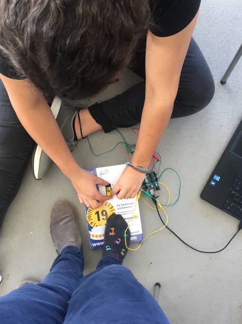 Determining of the threshold Determining of the threshold | 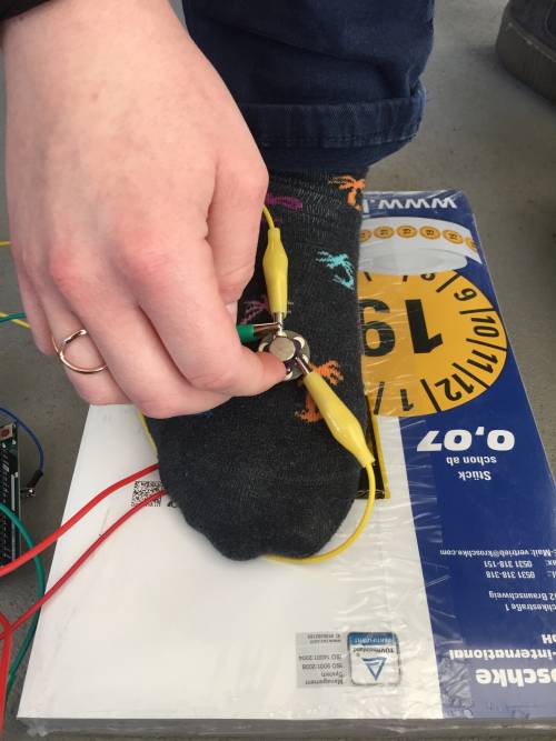 Looking for the right place for the LilyPad Vibe Board |
Programming the attiny85 & soldering the connections
 First rough sketch | 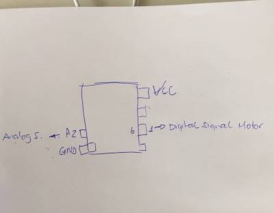 Attiny85 connections Attiny85 connections | 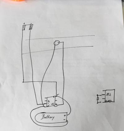 Electric wire connections for the sole |
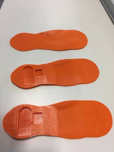
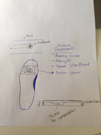
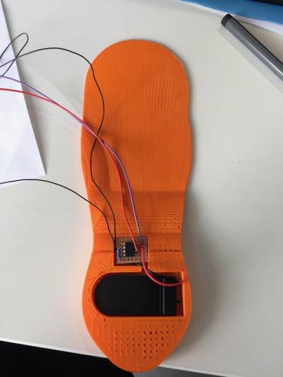
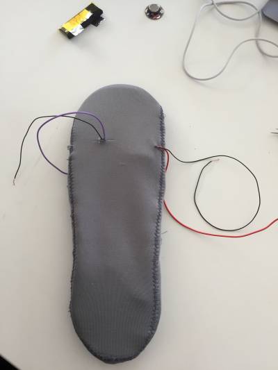
This first rough sketch shows our first placement idea. The LilyPad Vibe Board will be attached on a kind of belt. The only change we made for our final prototype was to put all electrical components in the back of the sole. The reason for this is that we then can increase the high of the sole in the back, that way we are able to build pockets for the components which will help for a more comfortable wearability.
One of the last steps was to program the Attiny85 and solder electric wires to it.
We decided to solder the 15kΩ resistor between A2 and GND of the Attiny85.
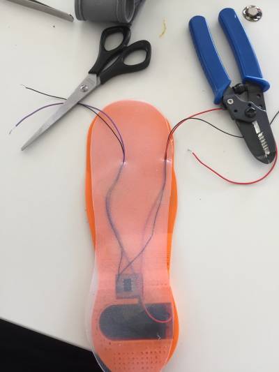
Besides that we also decided to cover the cables with an layer of EcoFlex for protection and additional comfort for the wearer.
 |  |  |