Fabricademy FINAL PROJECT: the Aptus Sole
The theme for the projects of the Fablab Kamp-Lintfort was Personal fabrication for Care – creating something with the purpose of having a helping, therapeutic or assisting purpose. Together with Pia and Natalia, I worked on a project developing a sensor based, user-adaptable insole with over-pronation detection and integrated feedback. Put simply, the sole detects when the wearer is walking incorrectly and with a quick vibration alerts the wearer and in this way, it aids in gait correction while simultaneously providing the foot with the support it needs
What?
Over pronation is defined as an excessive inward rolling of the foot or an extreme inward pronation. This condition is often called flat foot. The opposite, supination, involves the foot being rolled excessively outwards. The aim of the Aptus sole project is to develop a sensor embedded sole that provides a feedback if over pronation is detected. In this way, the Aptus Sole with help with the condition as well as prevent it from worsening. The gets it's name from one of it's characteristics - being able to adapt to every wearer
Why?
Effects of pronation vary depending on the degree of intensity. In the case of runners, over pronation can result in shin splints, Achilles tendinitis, runner's knee and plantar fasciitis. The ideal case would be an Aptus sole for children as it could help in treating the problem and 'reminding' the child to walk properly
How?
In short the process can be condensed into 3 main parts:
- Obtaining wearer’s data
- Sole and sensor development
- Assembly and testing
1. Obtaining wearers data
What makes the Aptus unique is the fact that the sole is completely adapted to the wearer’s needs and conditions. The process starts with a 3D scan of the wearer’s foot being made. In this way, the exact topography of the foot can be determined. Once the foot has been scanned, this scan is then used to make the base sole as every wearer has specific needs regarding amount of support. The pressure threshold of the wearer will also have to be determined.

2. Sole and sensor development
Flexible bottom
An essential part of treating over pronation is providing enough support to the affected foot. Therefore this will also be incorporated into the Aptus sole. The bottom of the sole will have to be rigid as well as flexible in order to support and move with the foot. By combining different design elements and techniques, such as mesh structuring and specialised material, 3D printed items can have these characteristics. The material used will be flexible filament as this is a highly versatile polymer, enabling different support variations to be made (e.g more support in midsole or heel area). 3D printing is the preferred method as it provides a low cost solution, with the added benefit of being able to quickly altering the design and seeing the new result in a few hours. The 3D sole will be flat with a rigid, raised midsole to give the arch of the foot support.
Soft upper
Although support is an integral part of the sole, comfort is another deciding factor to the total effectiveness. Factors that have to be considered for the final material are, stability, flexibility and skin tolerance. The upper will comprise of a thin EcoFlex layer which is molded into the shape of the base sole. EcoFlex is a durable, flexible silicon based material that is cheap and easy to use. The final EcoFlex is a mixture of 2 components; It is easy to prepare and ready within a few hours. The soft layer will also be covered in a thin cotton material to increase comfort and wearability.
Sensor development
The Aptus sole is based on a simple input and output system. The input being the incorrect, over pronated gait, and the output being the vibration. The input can be defined as the excessive inward rolling of the foot, therefore there will be an increase of pressure on the base of the big toe. Once the predetermined threshold of pressure has been detected by the pressure sensor the wearer will be alerted through the vibration feedback. Instead of placing the sensor at the bottom of the foot to measure the pressure of the whole body e.g on the ball of the foot, the sensor will be placed on the side of the sole (base of big toe) so as to measure the pressure only when the foot rolls inward. The sensor will be programmed using Arduino micro controlling as this was used throughout the Fabricademy course. By using an “if statement” the progamme can evaluate the situation and give the vibration output if the pressure detected is over that of the predetermined threshold.
3. Assembly and testing
The assembly comprises of the 2 bodies of the sole, the soft upper and the flexible lower, being joined into the final sole. In this step it is important to make sure the final result is a homogenous object. In order to test it, the wearer would have to place the sole into the shoe and walk around with it. In the end we also decided to make a casing made of neoprene - this is washable and adds to the comfort
Before the sole is tested on the wearer a quality assessment will be done to ensure customer satisfaction:
Quality assessment:
- Is the feedback sensor working?
- Is the sole one piece, is it glued together properly and neatly?
- Does the sole prescribe to the initial measurements i.e. will it fit into the wearer’s shoe?
- Once the sole has undergone a quality assessment the sole can now be tested on the wearer
Testing process:
- Over pronation sensor – is the feedback being delivered at the right time and with the right amount of intensity for the wearer?
- Fit – Does the sole fit properly into the shoe, is it too big or small?
- Overall comfort – Does the wearer have any complaints regarding the materials?
- Are there sharp edges that could potentially irritate/ hurt the wearer?
Once the wearer has tested the sole with different shoes, the necessary adjustments can be made. These could be, amongst others, adjustment of the feedback sensor – if the vibration is too hard or too soft or changing to a different cover or adding midsole support material
HOW IT WORKS:
The sensor measures a value and if this value is higher than the predetermined threshold (which we tested ourselves), the vibration sensor goes off. Because we didn’t want the vibration to occur every single time there was even the slightest incorrect movement, a delay of 1,5 seconds was added.
Technical components
We programmed the Lilypad Vibe Board with Arduino. After about a million different versions of code, we finally got the result. The code was then uploaded on to the Attiny85. All these connections were soldered onto a small PCB. The battery pack was also essential and was also connected. A 15kohm resistor was also used to keep the readings in a range that was easy to work with.
| DIY Pressure based sensor | |||
 |  |  | |
| Output feedback - vibration from Lilypad Vibe Board | |||
 |  |  | |
Errors and modifications
Initial sensor ideas:
- Make our own sensor
- Use a 50kg load cell
After many failed attempts of using the load cell we decided to make our own sensor based on wearables 1 and 2. Normally load cells are used in combination (e.g in a scale, 4 are used together using a load cell amplifier.) In our case the connections and ports weren't working like we wanted.

Our final sensor is a very simple, using conductive and non conductive material, it works on the following principle – applying pressure closes the circuit and the threshold is reached allowing the vibration in to go off. For more details on the failed attempts and info please visit Pias Wiki and Natalias Wiki
Making the sole:
The first prototype was a definite learning curve. We attempted to use online parametric software ( Gensole) to make the sole and 3D printed it using PLA. The result – a solid piece of plastic that could probably be used to knock someone out. We also didnt design any support on the sole so we experimented with 3D printing little supports to figure out how the dimensions should be. First attempt - something that resembled a lego piece, and when stepping on it, lso felt like stepping on a lego.
| First prototype | |||
 | |||
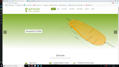 | 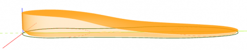 | 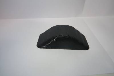 | |
| Gensole software | Sole designed in Gensole | Midsole support | |
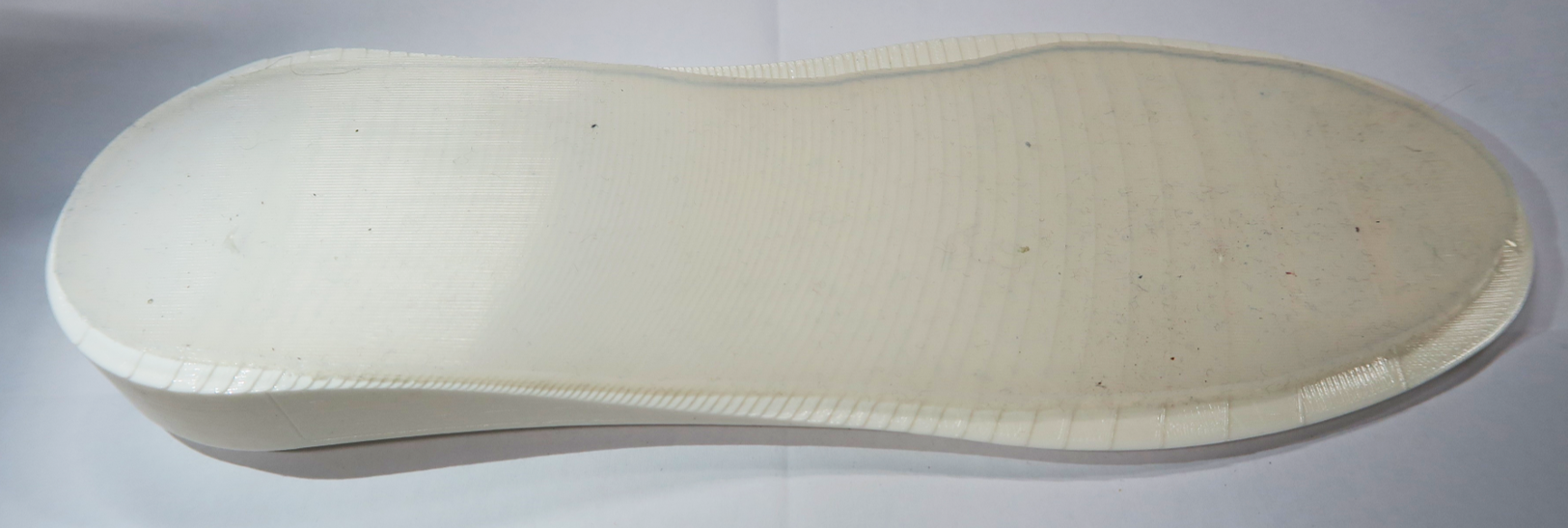
Back to the drawing board – Using the skills we learned about modelling programmes like Rhino and Fusion 360, we made a sole with exact measurements of Pia’s foot (Pia was our test subject because she over pronates). At this stage we also consulted with our mentor Anastasia as to what materials we could use. She suggested flexible filament which we were lucky to have in the lab! We printed the next prototype with the flexible filament and the outcome was great! We added a support to the middle so now it actually resembled an insole.
The next steps included altering the sole by adding little compartments for the technical components (battery pack, Attiny85 and cables). I did this by extruding the base and extruding the smaller compartments.

FINAL
 |  |
Improvements :
- Making the product more aesthetically pleasing and not so bulky
- Using a more precise method of determining the threshold
- Using a child as a 'test subject'. Because we want to help in the prevention of the effects over pronation, we think it would be ideal for children to use the Aptus sole.
Overall, I am happy with what we made. We learned a lot and it was challenging at times but we enjoyed it.
Thank you to all who helped in any way in this project!