Aptus Sole – Final project results
Our final project is based on the idea to produce an insole with an embedded sensor which gives the user a feedback via vibration when there is an overpronation. Overpronation is defined as an excessive inward rolling of the foot. The target group are mostly children in the developmental age because they have the chance to correct their walking behaviour before it is too internalized. The big advantage of this sole compared to a normal orthopaedic sole is that it does not fight against the problem itself but attacks the problems origin. First, we needed to produce the sole itself. We wanted to produce a 3D-printed sole with support. After we completed this step, we also poured an EcoFlex layer over the print to increase the wearing comfort. As a last step we added an exchangeable cloth layer for hygiene and longevity. The next step was to get the technical part done. In general, we needed two different components. First the pressure sensor, for the input signal. Second the vibration sensor, for the output signal. To make them work together we needed a microcontroller with a code which defines the relation between the input and the output signal. We wanted to build the input-sensor on our own because we learned the necessary basics in the topic “E-Textiles and Wearables I”. The output-sensor is a Lilypad vibration-board. Our preferred microcontroller is an ATtiny85 because according to its size it is easier for us to integrate it into our sole. Because of the great Arduino-software-library we were able to use an already completed code. The only thing we had to do was to adjust the code to our pins.
Approach and Development of a Prototype
First, I designed a pattern for the 3D-print with Rhino. For this purpose, I took a picture of a foodstep as an orientation. According to the knowledge that the person had size 40/41 I then adjusted my design.
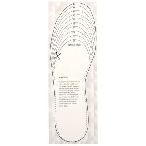 Pattern for first 3D-print
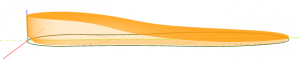
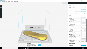
When the 2D pattern in Rhino was finished I further processed it with Fusion360. Using the Extrusion-function I transferred it into a 3D object. To prepare the sole for the 3D-printer Ultimaker 2+, I opened the 3D-object with the software Cura and made the necessary settings. Necessary settings are for example the layer height, the wall thickness, the infill density, the print speed and many more, which are shown in the following picture.
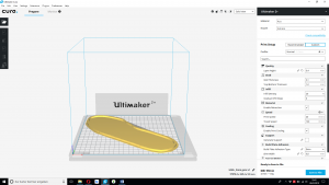 Necessary settings for the 3D-printer
Parallel to the printing of the first pattern I designed a second pattern, but this time for the EcoFlex layer. For this purpose, I took the first drafted foot again and added a 2mm high frame. I designed this pattern to have a foundry mould in which I can easily pour the EcoFlex.
 Settings for the EcoFlex-pattern
After the finished printing process, I was able to test the sole on our proband and fortunately it fitted in the first attempt. Thus, we were able to work on the next step. According to the fact that a person who suffers from overpronation needs support in the foots middle our focus changed to that circumstance. To design this support, I chose Rhino again. First, I inserted the 3D-scan of our proband's foot as an orientation. Especially, I looked at the hole between the floor and the foot's inside. After completing the draft and extruding it with Fusion360, I was able to print again.
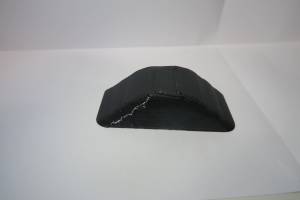 First support
Unfortunately we noticed that the support was no support because our proband was in pain while stepping on it. After that failure we decided that we needed to take other perspectives into consideration. According to this, we decided to get help from professionals. We had a meeting with workers from Hodey to which we presented our project. After that we received a constructive feedback. Luckily for us, one of the workers was Mr. Kai Gau, who also invented and produced a customizable sole some years ago. He gave us the advice to go to a website named “Gensole”. This website automatically constructs a sole by just using a 3D-scan.
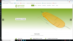 Gensole-Homepage
In the following there is a picture of the website and also one of our sole which is adjusted to our probands 3D-scan.
 Automatically adjusted sole from the website Gensole
Because all of our group members were satisfied with the construction I prepared it for the 3D-print using Cura again.
 Settings for the 3D-print of the Gensole-sole
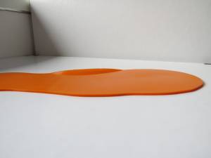
After the finished printing process of the Gensole-sole, our proband tested the wearing comfort again. Because of the much smoother transition between the sole and the middle support our proband confirmed it as well fitting. Thus, I completed the lower part of our sole, composed of the 3D-print and an EcoFlex layer.
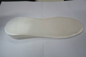 First „Aptus Sole“ prototype
Technical part and modifications of the design
Because of this achievement, I could focus on doing the required technical part for our project. During the course and especially during the classes of “E-textiles and Wearables II”, I used an Arduino-code with the same principles: pressure as input and a blinking LED as output. The only difference is that we have a vibration board as an output instead of the LED. Due to this, I did not think that it would be such a challenge to acquire the appropriate code. Bad luck, it did not work like expected and that is the reason why Pia did the whole programming part. But I will give you a short overview what belongs to our technical part – to carve out an Arduino-code fitting our conception, connecting all required parts for the final product together that is pressure sensor, vibration board, resistor and ATtiny. To prepare this, the pressure sensor has to be constructed. Based on the gained knowledge from the weeks of e-textiles and wearables, we used two pieces of semi-conductive fabric and one conductive fabric to create our DIY-pressure sensor. With finalizing our pressure sensor, we could arrange and set up our circuit. After testing several self-written or found-on-the-internet codes and several failures, we looked up the provided Arduino-libraries and found a code, which meets all our conditions. But if you want to get some more details about this part, just go to Pia’s page – she explained her part more precise.
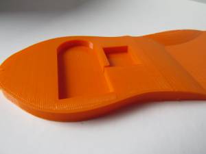
Simultaneously, we had various questions, which were for instance: How can we connect the sole with the technical part? Should the wearer walk onto the technical part, running the risk of destroyed parts? Is there a possibility to integrate the technical part into the sole – what about designing gaps and pockets for this? The first prototype was printed with the common PLA-filament of the 3D-printer, there was no indication of flexibility – it was like walking with a plank underneath the foot. And this was not what we wanted to achieve with our sole. In addition to that, we did not like the height of heel’s area, so we decided to redesign and improve the design of our sole. Concerning the form and size of the sole, we orientated on our first prototype. This time, we added the side warded support for the metatarsus by ourselves and reprinted the sole. We printed it before adding anything else because we wanted to test this kind of support. To get to know if this support has to be optimized or not, our proband tested the sole and confirmed to fit well.
 New design of the sole including support for the metatarsus
Based on this, we thought about how to create the support for the heel area of the foot. While thinking about this, we got the idea to increase the height of this area, so that we can design gaps and pockets where the technical part can be easily put into it. The main aspect to be considered was, that the wearer should not feel that he or she is walking on electronics – the wearing comfort should not be influenced. Another reason for designing this way was that we wanted to ensure, that the technical part will not be destroyed while using the sole.
 Sole including gaps and pockets for the technical part
Having our 3D-printed sole with the final design available, we tried to integrate the technical part into the designated gaps and pockets. Wild-goose chase – the gap for the battery holder was a little bit too small so that the on-off switch did not fit into it. Therefore, we did some modifications on our sole in Fusion360 and increased the size of the gaps and pockets. After reprinting our sole with the 3D-printer and a perfectly fitting technical part, we accomplished our final bottom of the sole. Now we could proceed with connecting all parts together and soldering the cables.
Sole including gaps and pockets for the technical part
Having our 3D-printed sole with the final design available, we tried to integrate the technical part into the designated gaps and pockets. Wild-goose chase – the gap for the battery holder was a little bit too small so that the on-off switch did not fit into it. Therefore, we did some modifications on our sole in Fusion360 and increased the size of the gaps and pockets. After reprinting our sole with the 3D-printer and a perfectly fitting technical part, we accomplished our final bottom of the sole. Now we could proceed with connecting all parts together and soldering the cables.
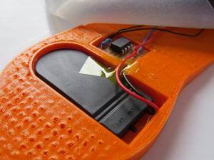 Final design of the sole with integrated technical part
After deciding to increase the wearing comfort by adding a finishing coat out of Neoprene, we fixed the positions for our sensors and attached them. For the vibration board, we added a strap, which runs over the wearer’s foot and makes sure the sensor will stay in its place. The pressure sensor has its position in the height of the base of the big toe. The reason for this is that this is a known print position of overpronation.
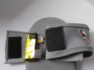 Positions of the sensors
Because of adding this finishing coat, we had to conduct the cables through the EcoFlex- and the cloth-layer. After that we soldered the cables to their required places, to ensure that the connections will stay in place while using the sole. After completing this step, I sewed another cloth layer over the pressure sensor. The reason for that was that in the latest tests the pressure sensor as well as the cables slipped out of their desired position. It also makes the sole look more aesthetic.
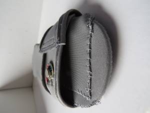 Protection for the pressure sensor
With the help of these steps we finalized our final project for the Fabricademy and are happy that we were successful and let our project idea come true!
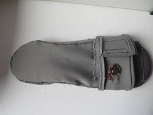 Our „Aptus Sole“
Here I add our final presentation including the testimony video! :)