FabLab Session l 17.01.2018
Today I started my first prototyping. We had some chats with Mika (Tutor of E-Textiles and Wearables 1) and she sent me some inspiring ideas. see http://www.kobakant.at/DIY/?p=6927
On basis on her design I sketched my first sole with a sensor out of textiles which works as a potentiometer triggered by pressure.

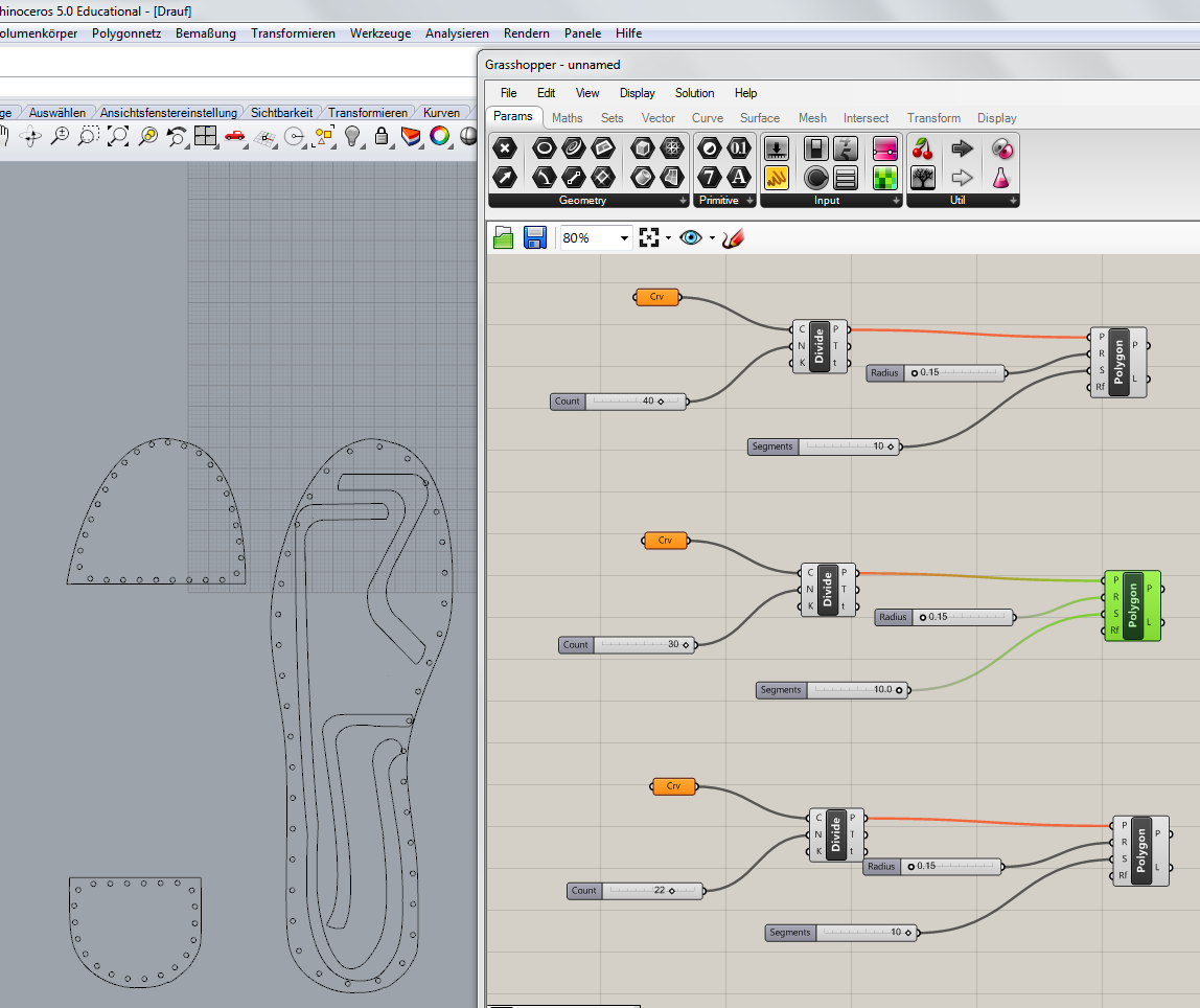
My first step was to look for a picture of a sole. I found one which I converted from a jpg. file to an svg file. With Inkscape I saved this file as a pdf. Now I was able to import the lines of the sole into rhino and work with them. Mika said in her description that it could be helpful to punch holes to neatly sew through thick felt with a non-conductive thread. I used grasshopper to punch the holes in all my components. I drew the thick lines to laser cut it later on out of conductive material.
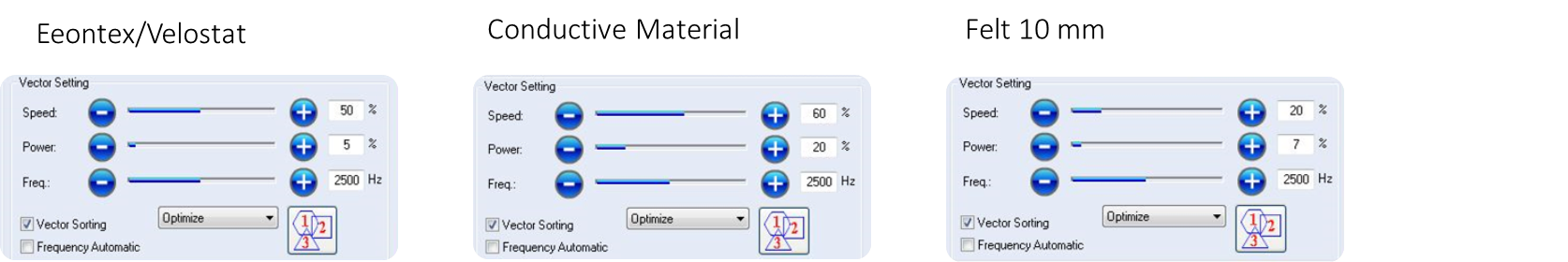
To save material I used a very small scale of my first cut of the sole. I cut my material in the lasercutter with the following settings:
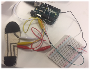
The result was this tiny sole:
By using Alligator-Clips I connected the Sole via a breadboard with a Arduino Uno. In detail, I connected the long conductive line to ground, not directly because to absorb too much energy I included a resistor of 10K Ohm. Furthermore, I connected the same line to A0 which is the pin for analog input, which provides the values at the end on the Arduino Screen. I connected one of the short line with the voltage supply pin (5 V). By covering the two lines with the semi-conductive Eeontext/Velostat and pressuring it I closed the circuit. To measure the real values I started Arduino and chosed Examples, 03 Analog, Analog InOutSerial. The values chaged by changing the amount of pressure . This was the first big success of the day :)

I realized that the maximum values where reached just by putting minimal pressure with my fingers. Therefore the next steps where to create a sole in my real size to test how the create the proportion between conductive and semi-conductive material.
18.01.2018 l FabLab Session
I started the day to reconstruct my sketch in Rhino. I wondered if i will get better values by get rid of two zones like in my first example and to cover the whole sole with conductive material. I thought with it I am able to catch all load independent on which zone of the foot it will occur.

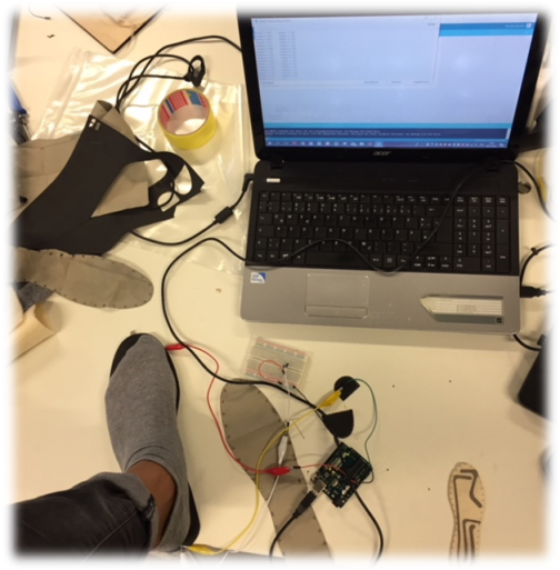
The big part was cut out of the semi-conductive material and the smaller parts with the holes (for sewing orientation) out of conductive material. added some additional zone to put on the Alligator-Clips and to ensure that the conductive material will not touch. I connected the parts as mentioned before with Arduino Uno via the breadboard. And the good news were the values were changing by putting pressure on the sandwich of sole (conductive, semi-conductive, conductive). But the same problem occurred the maximum values were reached by putting really few load on it. I was wondering what happens if I connect the semi-conductive material with A0 and to ground and I figured out that I am able to produce values as well but in a broader scope which seems logical because the overall resistance is higher by using only one conductive than using two high conductive parts of material.
This finding was a step closer to what I am looking for. At the end the sensor should deliver values from a range from 0 up to 150 kilograms (*9,81 = 1471,5 Newton). But following this principle I started to test the scope of values by using the whole semi-conductive sole but only a part of conductive material. I tried it with my whole body weight by stepping on it. This was the first time I did not reach the maximum value.
Following the latest findings I did a new sketch for the cut of conductive material. I used Adobe Illustrator to draw the lines which was more difficult than I thought for me because I have never really worked with this system before. With some support of my team mates I came up with this sketch:

FabLab Session l 20.01.2017
My idea with the conductive material failed.
The values I got where highly inconstant.Furthermore, the values in non-operating state where really high. Hence, I tried to use conductive foam instead of Eeontex because the material contracts better without load which reduces conductivity. The good thing im far away from the max. value but the values I was gathering are quite small and the differences between by changing the load was not significantly. The scope was from 80 - 180.
I tried to put the conductive material in two parts (without contact) on the semi-conductive foam the values have been in the range from 55 to 400.

https://learn.sparkfun.com/tutorials/lilypad-buzzer-hookup-guide/triggering-sounds: Code for Buzzer Melody
