WEEK 05 | 24.10.17
E-Textiles & Wearables I
This week we learned about electronics applied in textiles. The Kobakant team was invited to explain the main topics of this field and they gave us some sample work as an introduction to this magic world of circuits, microcontroller, conductive fabric, and threads.
Here is the Kobakant page for more exploration.
Electricity: The basics
It is very important for people who have never worked on this field to explain basic concepts of electronics.
Here I found a good explanation about it.
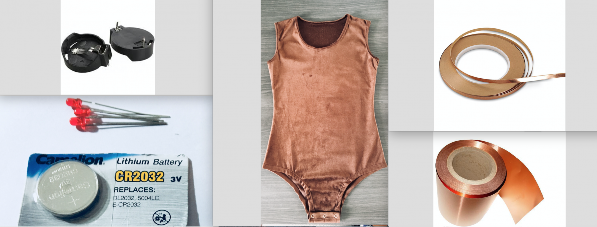
Application 01 | Making a circuit
In this exercise I wanted to explore a basic circuit without using a micro controller so I based my experience on this previous example.
Tools:
- Sellotape
- Soldering iron
- Scissors
- Multimeter
Components:
- Red Axial LED (or Green or yellow)
- CR2032 Coin Cell Battery Holder
- CR2032 Coin Cell Battery
- Copper Tape (1/4″)
- Copper flexible piece
- A garment
Schematic:
Related Video: Intro to Schematics
After I saw this short video, I draw my first schematic circuit for this exercise.


Process:
1. Paste the copper tape into the garment in the shape of the design.
2. Cut the circular pieces of the push-up button
3. Solder the copper tape circuit where is necessary
4. Use the multimeter to check electrical continuity along the process.
5. Just after that, start soldering the components. Firstly, the coin cell battery holder and secondly the circuit made with the copper tape.
6. Finally, I checked if it was working as I expected.


Tips:
Use sellotape to protect the copper tape when crossing circuit lines.
Troubles:
In my first attempt, I started working without drawing a schematic on paper so I made a closed circuit forgetting to leave the negative line open to close the circuit by the push-up button so the circuit doesn't work.
After that, I draw the schematic circuit on paper making sure that I was not missing any detail. So then, my circuit finally worked!
Application 02 | ATtiny 45 - 1st Attempt
In this exercise I planned to use a microcontroller ATtiny45 in my circuit. This was my first attempt and it only worked for a while, so that I tried a new circuit as I will explain some lines below.
References:
http://highlowtech.org/?p=1695 (Programming an ATtiny with arduino)
http://highlowtech.org/?p=1706 (Arduino board as ATtiny programmer)
https://www.youtube.com/watch?v=Z5flBzWltVE (ATtiny 45/85 programming | Spanish tutorial)
Components:
- 02 ATtiny 45
- 02 CR2032 Coin Cell Battery Holder
- 02 CR2032 Coin Cell Battery
- Copper flexible piece
- 06 LilyPad LED White
- 06 LilyPad LED Orange
- 02 Pin header 1×6
- 04 Pin header 2×2
- 04 Resistor 10K
- 04 Push button
- Ribbon cable
- 12 embellishment pieces
- A garment
- Thread and needle
Tools:
- Soldering station
- Soldering iron
- Soldering paste and tin
- Scissors
- Multimeter
Machine:
- Roland CAMM-1 Pro GX Vinyl Cutter

Software:
- Eagle
- Fab Modules (Vinyl machine program to cut the flexible PCB)
- Editor to edit the PCB board image
Note:
It is super necessary to download the ATtiny library and add it to Eagle, otherwise the components we are going to use will not be available in the current library that the program already has.
This tutorial is for people who have never used Eagle software. It has a nice program explanation.
Inspiration:
I was inspired by the octopus and its luminescence under the water, so that I decided to use some LEDs as a representation of the octopus sucker that would be controlled by push buttons located on the sides of the garment.

Some ideas:
Here are some sketches of the garment design. Finally, I decided to develop the first sketch.


Process:
For the circuit
1. Design the schematic circuit in Eagle program.
2. Design the PCB very accurate to fit into the vinyl cutter machine. Flexible copper width: 12 cm.
3. Edit the PCB image you got from Eagle for cutting. The image of the board would be always a positive image as you will see lines below.
4. Cut the circuit on the machine.
5. Transfer the circuit on a paper and put sellotape to keep it durable.
6. Solder the circuit components very carefully, specially the ATtiny 45.
7. Use the multimeter to check electrical continuity along the process.
9. Just after that, finish soldering the rest of components.
10. Finally, I checked if it was working as I expected.
For the design of the garment
1. Design the shape of the embellishment pieces in a 2D program (Rhinoceros, Autocad, etc.)
2. Cut this pieces on the laser cutter machine.
3. Sew the embellishment pieces on the garment.
4. Solder the lilypad LEDs on the garment
5. Use the multimeter to check electrical continuity along the process.
Schematic:


Board:


PCB Images for cutting:

Development:

Files:
int led1 = 1; Definimos el diodo led en el pin 13
int boton1 = 4; Definimos la entrada del pulsador en el pin 2
int numeropulsaciones;
int contador;
int i=0;
void setup () {
pinMode(led1,OUTPUT);
pinMode (boton1,INPUT);
//Serial.begin (9600);
}
void loop () {
  int espera=50;
  int time=0;
  i=0;

  if (digitalRead (boton1) == LOW && millis() - time> espera) // He empleado la funcion millis para evitar el antirrebote
  {
    numeropulsaciones ++;
    //Serial.println (numeropulsaciones); // Imprime el numero de pulsacion en el Serial Monitor de Arduino//
  }
  if (numeropulsaciones == 6)// En el momento que se encuentre en el Case 6 vuelve a 0.
  numeropulsaciones = 0;
  switch (numeropulsaciones) // Dentro del switch he definido 6 cases, que cambiaran en funcion de las pulsaciones dadas.
  {
  case 0:
    digitalWrite(led1,LOW);// Apagamos todos los leds
    break;
  case 1:
    digitalWrite(led1,HIGH);// Encendemos todos los leds

    break;

  case 2:
    digitalWrite(led1,HIGH);//Encendido tira led 1
    delay(80);
    digitalWrite(led1,!HIGH);
    delay(80);
    digitalWrite(led1,HIGH);//Encendido tira led 1
    delay(80);
    digitalWrite(led1,!HIGH);
    delay(80);

    break;
  case 3:
    digitalWrite(led1,HIGH);//Encendido led 1
    delay(400);
    digitalWrite(led1,!HIGH);
    delay(400);
    digitalWrite(led1,HIGH);//Encendido led 1
    delay(400);
    digitalWrite(led1,!HIGH);
    delay(400);

    break;

  case 4:
      time = millis();
}
 delay (100);
}
Application 03 | ATtiny 45 - Final Attempt
After the last experience using the flexible copper and cutting the circuit in a Vinyl cutter, I decided to modify my circuit by choosing a better board for my circuit, so that I made my PCB in a harder and conventional material hoping this time it will work better.
References:
Here is a good documentation about preparing the files and using the milling machine (Roland MDX-20)
Components:
- 04 Layer PCB
- 02 ATtiny 45
- 02 Pin header 1×6
- 02 Pin header 1×4
- 06 Pin header 1×3
- 02 Pin header 1×2
- 02 Resistor 10K
- 02 Push button
- 06 LilyPad LED White
- 06 LilyPad LED Orange
- Ribbon cable
- 12 embellishment pieces
- A garment
- Thread and needle
Tools:
- Soldering station
- Soldering iron
- Soldering paste and tin
- Scissors
- Multimeter
Machine:
- Milling machine (Roland MDX-20)

Software:
- Eagle
- Fab Modules (milling machine program to cut the PCB)
- Editor program to edit the PCB board image
Note:
It is super necessary to download the ATtiny library and add it to Eagle, otherwise the components we are going to use will not be available in the current library that the program already has.
This tutorial is for people who have never used Eagle software. It has a nice program explanation.
Process:
For the circuit
1. Design the schematic circuit in Eagle program.
2. Design the PCB to be cut on the milling machine.
3. Edit the PCB image you got from Eagle for cutting. The image of the board would be always a negative image as you will see lines below.
4. Prepare the file to be mill on the machine. Here are some steps to follow.
5. Mill the PCBs.
6. Clean them by using a paintbrush or similar.
7. Solder the circuit components very carefully, specially the ATtiny 45.
8. Use the multimeter to check electrical continuity along the process.
9. Just after that, finish soldering the rest of components.
10. Finally, I checked if it was working as I expected.
For the design of the garment
1. Design the shape of the embellishment pieces in a 2D program (Rhinoceros, Autocad, etc.)
2. Cut this pieces on the laser cutter machine.
3. Sew the embellishment pieces on the garment.
4. Solder the lilypad LEDs on the garment
5. Use the multimeter to check electrical continuity along the process.
Schematic:


Board:


PCB Images:
For milling 

For cutting 

Preparing files Here is a good documentation about preparing the files and using the milling machine (Roland MDX-20)

Development:

Files:
int led = 1; Definimos el diodo led en el pin 1
int boton1 = 3; Definimos la entrada del pulsador en el pin 3
int numeropulsaciones;
int contador;
int i=0;
void setup () {
pinMode(led,OUTPUT);
pinMode (boton1,INPUT);
}
void loop () {
  int espera=50;
  int time=0;
  i=0;

  if (digitalRead (boton1) == LOW && millis() - time> espera) // He empleado la funcion millis para evitar el antirrebote
  {
    numeropulsaciones ++;
    //Serial.println (numeropulsaciones); // Imprime el numero de pulsacion en el Serial Monitor de Arduino//
  }
  if (numeropulsaciones == 5)// En el momento que se encuentre en el Case 5 vuelve a 0.
  numeropulsaciones = 0;
  switch (numeropulsaciones) // Dentro del switch he definido 6 cases, que cambiaran en funcion de las pulsaciones dadas.
  {
  case 0:
    digitalWrite(led,LOW);// Apagamos todos los leds
    break;
  case 1:
    // Endendemos y apagamos los led por intensidad
    for(int i=0;i<250;i++)
    {
      analogWrite(led,i);
      delay(10);
    }
    for(int i=250;i>0;i--)
    {
      analogWrite(led,i);
      delay(10);
    }
    break;

  case 2:
    // Hacemos una que los leds se enciendan y haga intermitencia
    for(int i=0;i<5;i++)
    {
      digitalWrite(led,HIGH);
      delay(80);
      digitalWrite(led,LOW);
      delay(80);
    }
    break;
  case 3:
    // Encendemos todos los leds
    digitalWrite(led,HIGH);
    break;

  case 4:
      time = millis();
}
 delay (100);
}
«« Back to Assignments
Week04 - E-Textiles & Wearables I << BACK___NEXT >> Week06 - Computational couture
«« Back to Students