Tilt sensor
For the Assignment of this week I decided to make a tilt sensor.
Scheme:

I start by choosing the fabric, I need one that is very conductive. Then, I do a test with the multimeter.

Once the conductivity is checked I choose the materials that I will use in my project:
• Conductive wire
• Conductive fabric
•Wool
• LEDs
• Non-conductive tissue
• Non-conductive beads
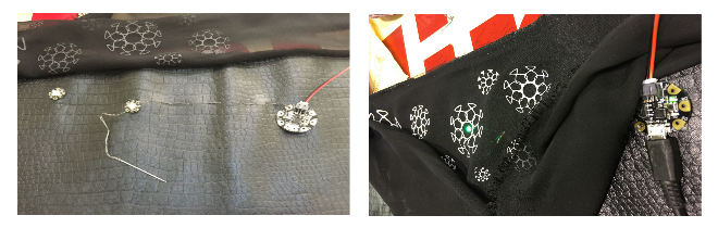
I begin by making a pompom with wool and conductive thread.
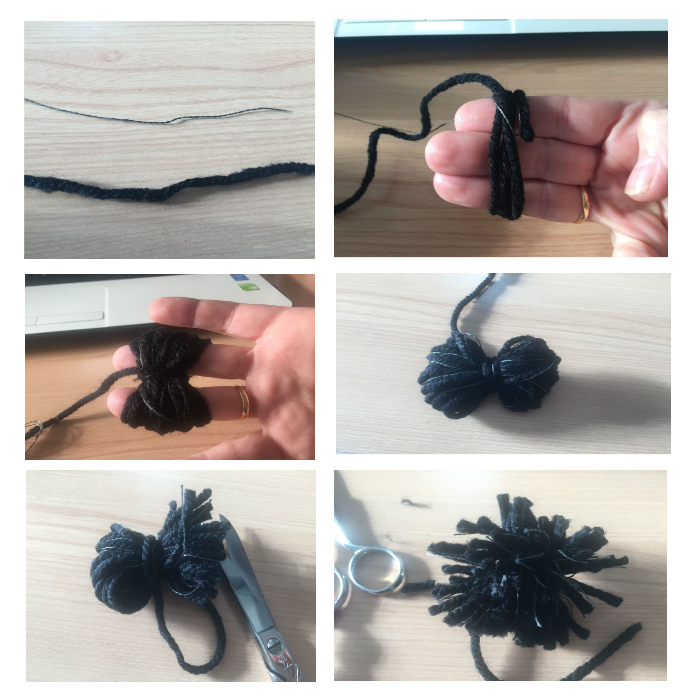
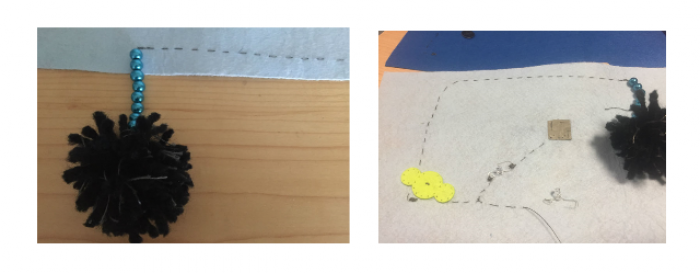
Then I put the beads to isolate and so have no problems if the cord touches some other thread.
I begin to sew following the scheme.
In order not to be confused with the pins of the leds I bend them differently, I bent the negative pin with a more rounded shape and the positive with a more square shape.
This way I can sew them perfectly and I know I will not make any mistakes.

Battery holders
Following the diagram, the part of the thread that comes from the pompom is the positive so I end up sewing on the fabric a few more stitches so that when I insert the battery, it touches the thread well.

I end up sewing the following leds and the battery holder.

ATtiny Programming
Configure ATTINY board:
1. Arduino preferences: Additional url card managers
2. Add: https://raw.githubusercontent.com/damellis/attiny/ide-1.6.x-boards-manager/package_damellis_attiny_index.json

- We close the manager
- In Tools
- Plate
- We go to Card Manager
- Search Attiny
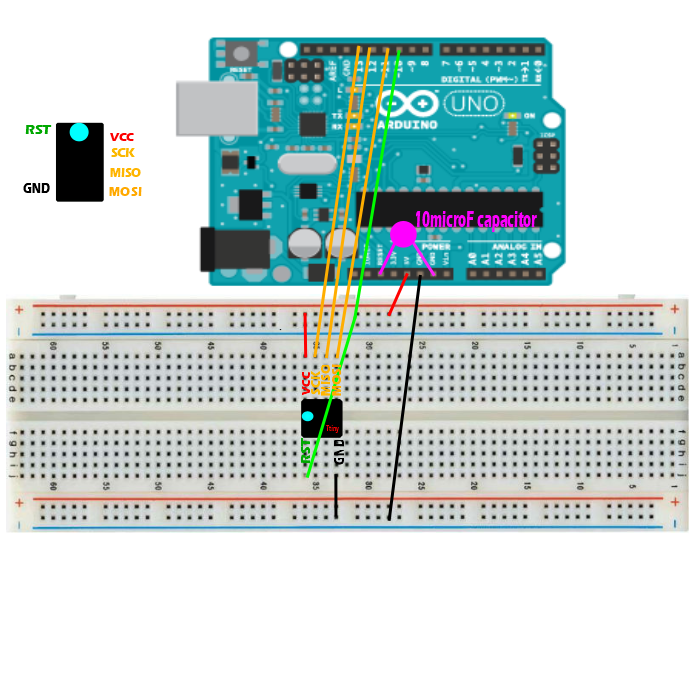
Using your Arduino ISP to program an ATtiny microcontroller
Thanks to Kobakant for his fantastic tutorial: http://www.kobakant.at/DIY/?p=3742
Burn Bootloader
To set the clock speed of your ATtiny to be faster (8Mhz) than the default of 1 MHz.
- Select “ATtiny45 (8 MHz)” in the “Tools> Card” menu
- Select “Arduino as ISP” in the “Tools> Programmer” menu
- Select “Burn Bootloader” in the “Tools” menu
Arduino as ISP
Loading sketch
- Open the sketch you want to load in ATtiny
- Select “ATtiny45 (8 MHz)” from the “Tools> Board” menu
- Select “Arduino as ISP” from the “Tools> Programmer” menu
- Load sketch.
If you get this error message, it's okay
avrdude: define the PAGEL and BS2 signals in the configuration file for the ATtiny85 part
avrdude: define the PAGEL and BS2 signals in the configuration file for the ATtiny8 part
Remove the capacitor when loading the Arduino ISP sketch to the Arduino Uno and replace the capacitor to record the boot manager and load any sketch on your ATtiny.
ATtiny Programming
Configure ATTINY board:
1. Arduino preferences: Additional url card managers
2. Add: https://raw.githubusercontent.com/damellis/attiny/ide-1.6.x-boards-manager/package_damellis_attiny_index.json
- We close the manager
- In Tools
- Plate
- We go to Card Manager
- Search Attiny
Turning your Arduino into a programmer of ISPArduino into an ISP programmer
Without condenser!
Download the Arduino software and install itArduino software and install it
Download the ATtiny folder and save it in the “hardware” folder of the Arduino folder sketchesATtiny folder and save it in the “hardware” folder of the Arduino sketches folder
Restart ArduinoArduino
Open the “ArduinoISP” sketch in the “Examples” folder
Select “Arduino” One “from the menu” Tools> Board “Arduino” One “from the menu” Tools> Board “
Select from the Tools menu> Serial Port
Load the sketch
Using your Arduino ISP to program an ATtiny microcontroller Add capacitors and programming connections! Arduino ISP to program an ATtiny microcontroller
With condenser!
Select “ATtiny45 (8 MHz)” in the “Tools> Board” menu
Select “Arduino as ISP” in the menu “Tools> Programmer” Arduino as ISP “in the” Tools> Programmer “menu
Select “Burn Boot Manager” in the “Tools” menu (yes capacitor)
Open the sketch you want to load in the ATtinyATtiny
Load sketch (yes condenser)
Now I connect my sensor to Attiny by adding a buzzer.
Scheme:
Code:
/*
CODE for the Fabricademy e-textile sensor swatch
first built for the Fabricademy 2017
Hannah Perner-Wilson and Mika Satomi, KOBAKANT
*/
#define sensorPin 3
#define speakerPin 2
#define ledPin 0
int sensorValue = 0;
int noiseFrequency = 0;
int ledBrightness = 0;
void setup()
{
pinMode(sensorPin, INPUT); use digital pin number here
pinMode(speakerPin, OUTPUT);
pinMode(ledPin, OUTPUT);
} void loop()
{
sensorValue = analogRead(sensorPin); use analog pin number here
MAKE SOUND:
if(sensorValue < 900){ noiseFrequency = map(sensorValue, 0, 1023, 100, 10000); noise (speakerPin, noiseFrequency); } FADE LED: ledBrightness = map(sensorValue, 0, 1023, 0, 255); analogWrite(ledPin, ledBrightness); } MAKE SOUND ON THE ATTINY WITHOUT THE SOUND LIBRARY: void noise (unsigned char noisePin, int frequencyInHertz) { long delayAmount = (long)(1000000 / frequencyInHertz); digitalWrite(noisePin, HIGH); delayMicroseconds(delayAmount); digitalWrite(noisePin, LOW); delayMicroseconds(delayAmount); }
Belt
I started cutting a rectangle of 95 x 22 cm in two different tissues. I chose synthetic leather to give body to the belt and tulle to decorate and hide the electronics.
For decoration I vectorized an image to cut it on textile vinyl.

I opened with Rhinoceros and I rised the design.
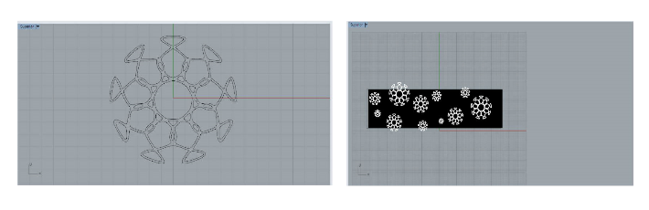
I cut the vinyl with a 45ºC blade that is usually the basic one with these parameters:
Speed: 24
Power: 130
Temperature at 167º (ask the seller, not all vinyls are ironed at the same temperature).

This week, we worked with Gemma v2 and 4 neopixel.
If you have Windows, download these drivers:
Then, open Arduino and configure the board:

Then, select USBtinyISP from the Tools→Programmer sub-menu

After installing the Arduino IDE with support for Adafruit's boards you can load a simple blinking LED example to test uploading to Gemma works as expected. Open the Arduino IDE and replace the sketch code with the following blink code:
Edit
Blink Gemma:
1. /*
2. Blink
3. Turns on an LED on for one second, then off for one second, repeatedly.
4.
5. This example code is in the public domain.
6.
7. To upload to your or Trinket:
8. 1) Select the proper board from the Tools→Board Menu (Arduino Gemma if
9. teal, Adafruit Gemma if black)
10. 2) Select the uploader from the Tools→Programmer (“Arduino Gemma” if teal,
11. “USBtinyISP” if black Gemma)
12. 3) Plug in the Gemma into USB, make sure you see the green LED lit
13. 4) For windows, make sure you install the right Gemma drivers
14. 5) Press the button on the Gemma/Trinket - verify you see
15. the red LED pulse. This means it is ready to receive data
16. 6) Click the upload button above within 10 seconds
17. */
18.
19. int led = 1; blink 'digital' pin 1 - AKA the built in red LED
20.
21. the setup routine runs once when you press reset:
22. void setup() {
23. initialize the digital pin as an output.
24. pinMode(led, OUTPUT);
25.
26. }
27.
28. the loop routine runs over and over again forever:
29. void loop() {
30. digitalWrite(led, HIGH);
31. delay(1000);
32. digitalWrite(led, LOW);
33. delay(1000);
If the blink works correctly, load the program for our neopixels.
Edit
Code:
#include <Adafruit_NeoPixel.h>
#define NUM_LEDS 4 Number of NeoPixels
#define PIN 1 DIGITAL pin # where NeoPixels are connected
IMPORTANT: Avoid connecting on a live circuit. . .
if you must, connect GND first.
Adafruit_NeoPixel strip = Adafruit_NeoPixel( NUM_LEDS, PIN) ;
void setup() {
strip. begin();
strip. setBrightness(100); 100/255 brightness ( about 40%)
strip. show(); Initialize all pixels to ' off'
}
void loop( ) {
for( int j=0; j<256; j ++) {
for( int i=0; i<NUM_LEDS; i++) {
strip. setPixelColor( i, Wheel1) ;
}
strip.show();
delay(20);
}
}
Input a value 0 to 255 to get a color value.
The colours are a transition r - g - b - back to r.
uint32_t Wheel( byte WheelPos) {
if( WheelPos < 85) {
return strip. Color(WheelPos * 3, 255 - WheelPos * 3, 0);
} else if(WheelPos < 170) {
WheelPos -= 85;
return strip. Color(255 - WheelPos * 3, 0, WheelPos * 3);
} else {
WheelPos -= 170;
return strip. Color(0, WheelPos * 3, 255 - WheelPos * 3);
}
}
Then, sew the circuit this way.
Edit
Circuit:


Finish making the belt.
To have the battery on hand and thus be able to turn on and off the belt, make a small cut on the fabric so that the battery is on the inside of the belt.
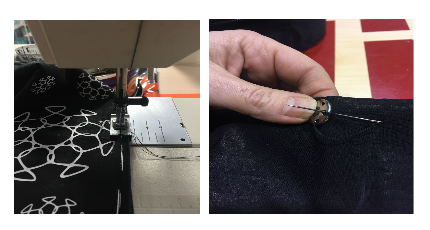
Fold it in half and machine sew.
Sew textile clasps at the ends to be able to close our belt.
Video: