This is an old revision of the document!
Sensor de inclinación
Para la asignación de esta semana, decidí hacer un sensor de inclinación.
Esquema:

Comienzo eligiendo la tela, necesito una que sea muy conductora. Luego, hago una prueba con el multímetro.

Una vez que la conductividad está marcada, elijo los materiales que usaré en mi proyecto:
• Cable conductor
• Tejido conductor
•Lana
• LEDs
• Tejido no conductivo
• Cuentas no conductoras
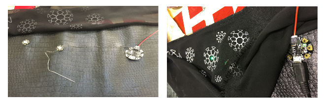
Comienzo haciendo un pompón con lana e hilo conductor.
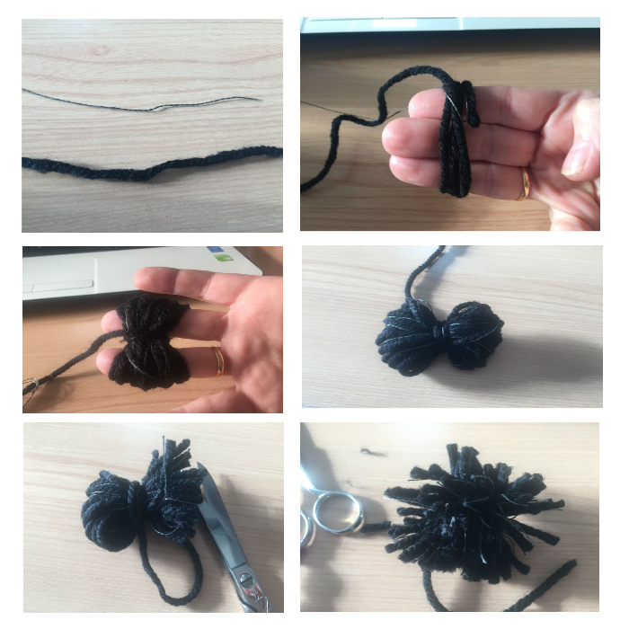
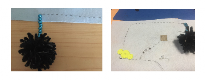
Luego pongo las cuentas para aislar y así no tengo problemas si el cable toca otro hilo.
Comienzo a coser siguiendo el esquema.
Para no confundirme con los pines de los leds, los doblé de forma diferente, doblé el pin negativo con una forma más redondeada y el positivo con una forma más cuadrada.
De esta manera puedo coserlos perfectamente y sé que no cometeré ningún error.

Titulares de batería
Siguiendo el diagrama, la parte del hilo que sale del pompón es positiva, así que termino cosiendo un poco más de puntadas para que cuando inserte la batería toque bien el hilo.

Termino cosiendo los siguientes leds y el soporte de la batería.

Programación ATtiny
Configure la placa ATTINY:
1. Preferencias de Arduino: administradores adicionales de la tarjeta url
2. Agregue: https://raw.githubusercontent.com/damellis/attiny/ide-1.6.x-boards-manager/package_damellis_attiny_index.json

- Cerramos el gerente
- En herramientas
- Plato
- Vamos a Card Manager
- Buscar Attiny
Usando su Arduino ISP para programar un microcontrolador ATtiny
Gracias a Kobakant por su fantástico tutorial: http://www.kobakant.at/DIY/?p=3742
Burn Bootloader
Para establecer la velocidad del reloj de su ATtiny sea más rápida (8Mhz) que la predeterminada de 1 MHz.
- Seleccione “ATtiny45 (8 MHz)” en el menú “Herramientas> Tarjeta”
- Seleccione “Arduino como ISP” en el menú “Herramientas> Programador”
- Seleccione “Burn Bootloader” en el menú “Herramientas”
Arduino como ISP
Cargando boceto
- Abra el boceto que desea cargar en ATtinyATtiny
- Seleccione “ATtiny45 (8 MHz)” en el menú “Herramientas> Junta”
- Seleccione “Arduino como ISP” en el menú “Herramientas> Programador”
- Cargar boceto
Si recibe este mensaje de error, está bien
avrdude: defina las señales PAGEL y BS2 en el archivo de configuración para la parte
AVrdude ATtiny85: defina las señales PAGEL y BS2 en el archivo de configuración para la parte ATtiny8
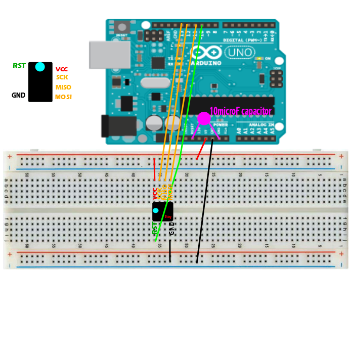
Retire el condensador cuando cargue el boceto de Arduino ISP en el Arduino Uno y reemplace el condensador para registrar el administrador de arranque y cargar cualquier boceto en su ATtiny.ATtiny.
ATtinyProgramación ATtiny
Configure la placa ATTINY: 1. Preferencias de Arduino: administradores adicionales de la tarjeta url 2. Agregue: https://raw.githubusercontent.com/damellis/attiny/ide-1.6.x-boards-manager/package_damellis_attiny_index.jsonATTINY board:
- Cerramos el gerente
- En herramientas
- Plato
- Vamos a Card Manager
- Buscar Attiny
Convirtiendo su Arduino en un programador de ISPArduino en un programador de ISP
Sin condensador!
Descargue el software Arduino e instale el softwareArduino e instálelo Descargue la carpeta ATtiny y guárdela en la carpeta “hardware” de la carpeta arduino sketchesATtiny y guárdela en la carpeta “hardware” de la carpeta de bocetos Arduino Reinicie ArduinoArduino Abra “ArduinoISP” “boceto en la carpeta” Ejemplos “ Seleccione” Arduino “Uno” desde el menú “Herramientas> Tablero” Arduino “Uno” desde el menú “Herramientas> Tablero” Seleccione en el menú Herramientas> Puerto serie Cargue el bocetoArduino software and install itArduino software and install it
ATtiny folder and save it in the “hardware” folder of the Arduino folder sketchesATtiny folder and save it in the “hardware” folder of the Arduino sketches folder
Arduino“ One “from the menu” Tools> Board “Arduino” One “from the menu” Tools> Board ”
Usando su Arduino ISP para programar un microcontrolador ATtiny ¡Agregue condensadores y conexiones de programación! Arduino ISP para programar un microcontrolador ATtinyArduino ISP to program an ATtiny microcontroller Add capacitors and programming connections! Arduino ISP to program an ATtiny microcontroller
Con condensador!
Seleccione “ATtiny45 (8 MHz)” en el menú “Herramientas> Junta”
Seleccione “Arduino como ISP” en el menú “Herramientas> Programador” Arduino como ISP “en el menú” Herramientas> Programador “ Seleccione” Grabar administrador de arranque “en Menú “Herramientas” (sí condensador) Abra el boceto que desea cargar en el boceto ATtinyATtiny Load (sí condensador) Ahora conecto mi sensor a Attiny agregando un zumbador.Arduino as ISP” in the menu “Tools> Programmer” Arduino as ISP “in the” Tools> Programmer “menu
Esquema:
vimeo>240630034?medium}}
Código:
/ *
CÓDIGO para la muestra de sensores de textiles electrónicos de Fabricademy
creada por primera vez para la Fabricademy 2017
Hannah Perner-Wilson y Mika Satomi, KOBAKANT
* /
#define sensorPin 3
#define speakerPin 2
#define ledPin 0
int sensorValue = 0;
int noiseFrequency = 0;
int ledBrightness = 0;
void setup ()
{
pinMode (sensorPin, INPUT); use el número de pin digital aquí
pinMode (speakerPin, OUTPUT);
pinMode (ledPin, OUTPUT);
} void loop ()
{
sensorValue = analogRead (sensorPin); usa el número de pin analógico aquí
MAKE SOUND:
if (sensorValue <900) {noiseFrequency = map (sensorValue, 0, 1023, 100, 10000); ruido (speakerPin, noiseFrequency); }LED FADE: ledBrightness = map (sensorValue, 0, 1023, 0, 255); analogWrite (ledPin, ledBrightness); } HAGA SONIDO EN EL ATTINY SIN LA BIBLIOTECA DE SONIDO: ruido nulo (ruido de char sin signo Pin, int frequencyInHertz) {largo delayAmount = (largo) (1000000 / frequencyInHertz); digitalWrite (noisePin, HIGH); delayMicroseconds (delayAmount); digitalWrite (noisePin, LOW); delayMicroseconds (delayAmount); }ATTINY WITHOUT THE SOUND LIBRARY: void noise (unsigned char noisePin, int frequencyInHertz) { long delayAmount = (long)(1000000 / frequencyInHertz); digitalWrite(noisePin, HIGH); delayMicroseconds(delayAmount); digitalWrite(noisePin, LOW); delayMicroseconds(delayAmount); }
Cinturón
Empecé a cortar un rectángulo de 95 x 22 cm en dos tejidos diferentes. Elegí cuero sintético para darle cuerpo al cinturón y al tul para decorar y esconder los componentes electrónicos.
Para la decoración, vectoricé una imagen para cortarla en vinilo textil.

Abrí con Rhinoceros y rematé el diseño.
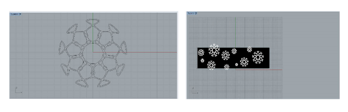
I cut the vinyl with a 45ºC blade that is usually the basic one with these parameters:
Speed: 24
Power: 130
Temperature at 167º (ask the seller, not all vinyls are ironed at the same temperature).

This week, we worked with Gemma v2 and 4 neopixel.
If you have Windows, download these drivers:
Then, open Arduino and configure the board:

Then, select USBtinyISP from the Tools→Programmer sub-menu

After installing the Arduino IDE with support for Adafruit's boards you can load a simple blinking LED example to test uploading to Gemma works as expected. Open the Arduino IDE and replace the sketch code with the following blink code:
Edit
Blink Gemma:
1. /*
2. Blink
3. Turns on an LED on for one second, then off for one second, repeatedly.
4.
5. This example code is in the public domain.
6.
7. To upload to your or Trinket:
8. 1) Select the proper board from the Tools→Board Menu (Arduino Gemma if
9. teal, Adafruit Gemma if black)
10. 2) Select the uploader from the Tools→Programmer (“Arduino Gemma” if teal,
11. “USBtinyISP” if black Gemma)
12. 3) Plug in the Gemma into USB, make sure you see the green LED lit
13. 4) For windows, make sure you install the right Gemma drivers
14. 5) Press the button on the Gemma/Trinket - verify you see
15. the red LED pulse. This means it is ready to receive data
16. 6) Click the upload button above within 10 seconds
17. */
18.
19. int led = 1; blink 'digital' pin 1 - AKA the built in red LED
20.
21. the setup routine runs once when you press reset:
22. void setup() {
23. initialize the digital pin as an output.
24. pinMode(led, OUTPUT);
25.
26. }
27.
28. the loop routine runs over and over again forever:
29. void loop() {
30. digitalWrite(led, HIGH);
31. delay(1000);
32. digitalWrite(led, LOW);
33. delay(1000);
If the blink works correctly, load the program for our neopixels.
Edit
Code:
#include <Adafruit_NeoPixel.h>
#define NUM_LEDS 4 Number of NeoPixels
#define PIN 1 DIGITAL pin # where NeoPixels are connected
IMPORTANT: Avoid connecting on a live circuit. . .
if you must, connect GND first.
Adafruit_NeoPixel strip = Adafruit_NeoPixel( NUM_LEDS, PIN) ;
void setup() {
strip. begin();
strip. setBrightness(100); 100/255 brightness ( about 40%)
strip. show(); Initialize all pixels to ' off'
}
void loop( ) {
for( int j=0; j<256; j ++) {
for( int i=0; i<NUM_LEDS; i++) {
strip. setPixelColor( i, Wheel1) ;
}
strip.show();
delay(20);
}
}
Input a value 0 to 255 to get a color value.
The colours are a transition r - g - b - back to r.
uint32_t Wheel( byte WheelPos) {
if( WheelPos < 85) {
return strip. Color(WheelPos * 3, 255 - WheelPos * 3, 0);
} else if(WheelPos < 170) {
WheelPos -= 85;
return strip. Color(255 - WheelPos * 3, 0, WheelPos * 3);
} else {
WheelPos -= 170;
return strip. Color(0, WheelPos * 3, 255 - WheelPos * 3);
}
}
Then, sew the circuit this way.
Edit
Circuit:


Finish making the belt.
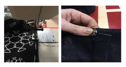
To have the battery on hand and thus be able to turn on and off the belt, make a small cut on the fabric so that the battery is on the inside of the belt.
Fold it in half and machine sew.
Sew textile clasps at the ends to be able to close our belt.
Video: