Week 09. E-textiles & Wearables II
Global Instructor : Becky Stewart
Class Outline
Slides available on https://speakerdeck.com/theleadingzero/fabricademy-wearables-and-e-textiles-ii
Introduction to microcontrollers and single-board computers Sensor circuits for microcontrollers (voltage dividers and pull up/down resistors) Actuator circuits for microcontrollers Hard-soft connections to a microcontroller Code reading Arduino examples (how to figure out what to copy and paste) Here are the videos that go with the Arduino Starter Kit examples included in the Arduino examples.
Assignment
Create an interactive object; if you are already experienced with coding, focus on fully integrating a microcontoller into a textile circuit. If you are new to coding, choose an example and get it working using your own sensors and actuators.
Hands On
First off all I'm trying to understand the working process of arduino and electronics so I had to study everything from the begining and made some experiences to see how to deal with them.
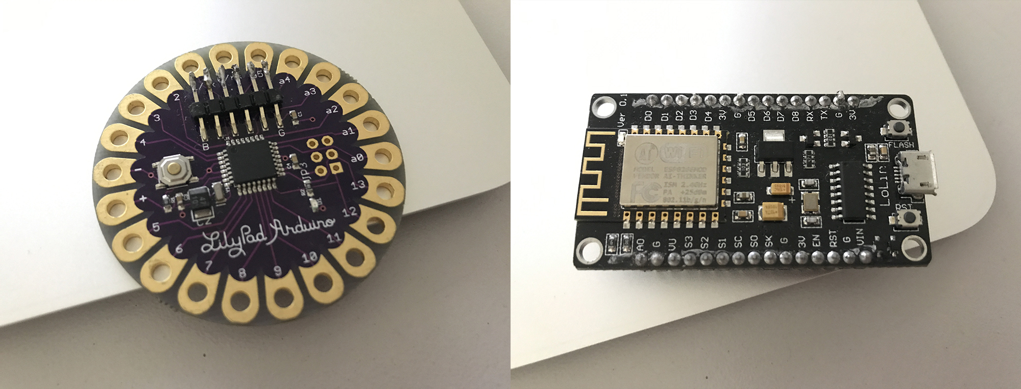
The Boards
Arduino UNO : basic board from Arduino
LilyPad Arduino : board used to wearables, is washble and have many types since simple ones with few ports until many complex ones with the connection USB inside.
Adafruit Playground: Is the most complete one with many sensors inside the board.
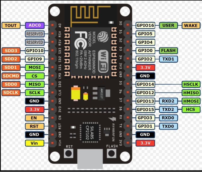
NodeMCU: a simple and alternative board that is cheapear and has already the WFI system to connect with the internet, so is useful IOT effects and control.
01. Blink
Searching for the tutorials I found a site with the maps of the connections in the basic exercises in Arduino, so I printed it and mount the basIC first exercise, that is to conNect a LED and make it blinks when the board is charged.
In this circuit I USED :
THE ARDUINO UNO BOARD
one LED
one resistor
and the connection cabells
one phrotoboard ( a board that facilitates the connections for testing or studying projects ).
Using Node MCU board
Blink One LED
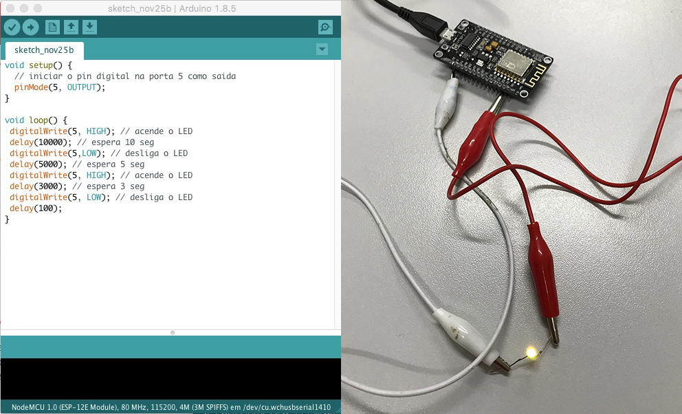
Now using the board to program the time to turn on the LED
Here the program is to : Turn on the LED, wait 10sec, tun off the LED wait 5 sec, turn on the LED , wait 3 sec, turn off the LED.
Link to the Code: https://drive.google.com/open?id=1yqwpWI4-NKriazUNCKEtLQwCX541IgJG
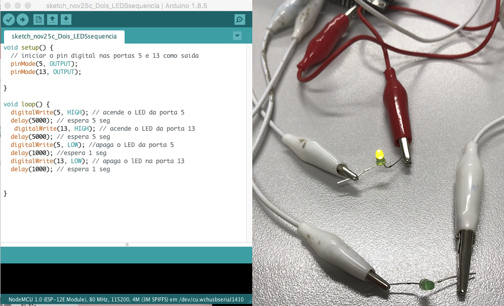
Blink two LEDs
Turn on the LED on port 5, wait 5 sec; turn on the LED on port 13, wait 5 sec; turn off the LED on port 5 wait 1 sec, turn off the LED on port 13 wait 1 sec.
Link to the Code: https://drive.google.com/open?id=1wjJ5hb0y65GpJ4bw0rN5wJ9tHpBzyzbA
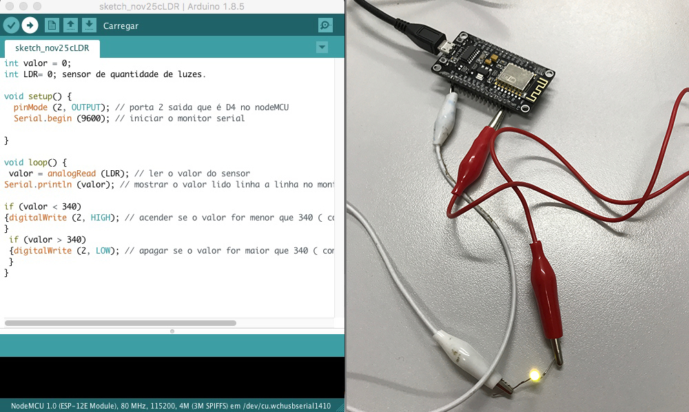
Blink one LEd with LDR (light sensor) used as digital sensor
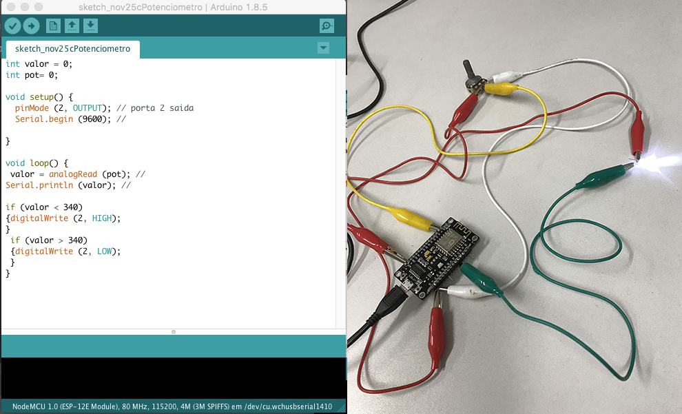
In this case I used the Serial Monitor to see the value of the light, and determine a range that could divide between light tuened onn and off , with this value I program to switch on and off the LED. Note that this use is very similar from that when used the potentiometer, and in the two cases, in spite of being analogical sensors we can use them like a digital one stablishing a value to swchit on and off.
Link to the Code: https://drive.google.com/open?id=1U7cBqMfbclaY15K8528cdOb2GuZm4QrJ
Blink one LEd with POT (potentiometer) used as digital sensor
Link to the Code: https://drive.google.com/open?id=11puM5j8Hs0iAyq9UQh89JaeQvD5xebsi
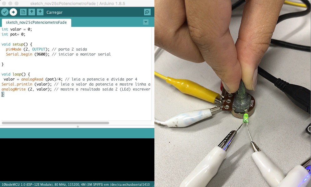
Blink one LEd with POT (potentiometer) used as analogical sensor
In this case I used the potentiometer to change the luminosity of the LED, between a range, so the sensor and the actuator both worked as analogical.
Link to the Code: https://drive.google.com/open?id=11puM5j8Hs0iAyq9UQh89JaeQvD5xebsi
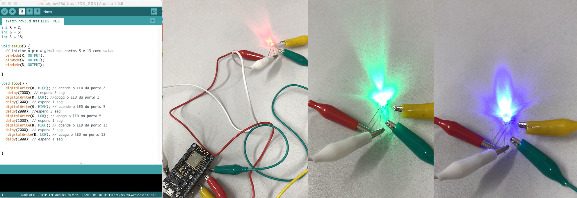
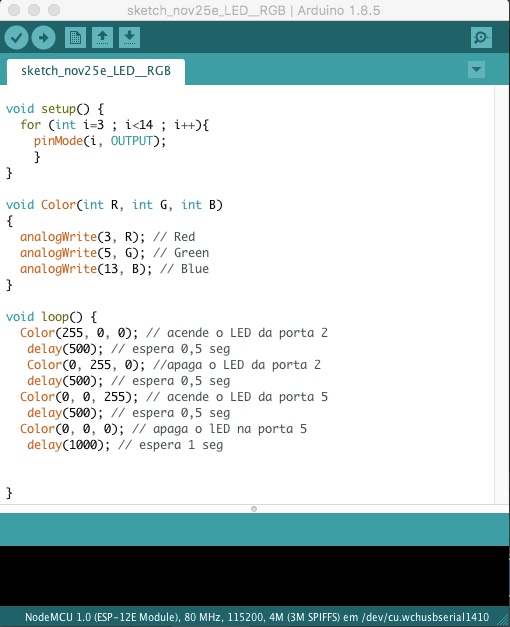
Blink LED RGB color by color in a digital way (on /off )
Link to the Code: https://drive.google.com/open?id=1XRAAOXot3Lp0Fc8uha01qYJagv2x8tqY
Blink LED RGB color by color in a digital way (on /off ), but selecting the composition of the color
Link to the Code: https://drive.google.com/open?id=1w7aX_BTCoqqSp-vaSOgFCItzS8rfqXF9
LED RGB color controlled by potentiometer
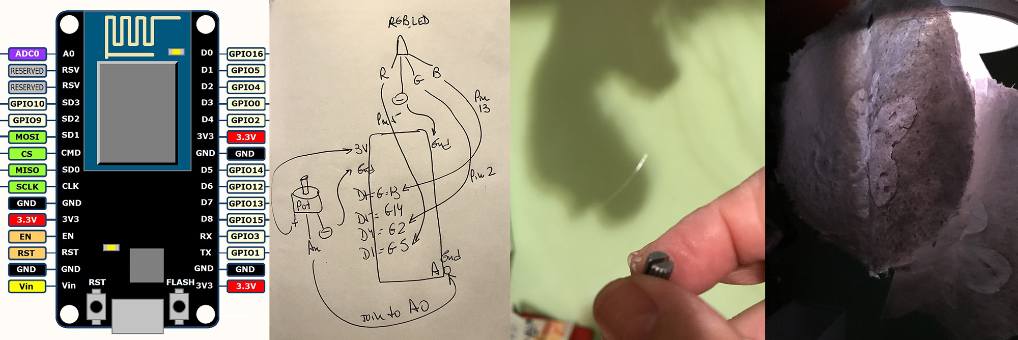
For the final weekly assignment I've chosen to instal a LED RGB light in a little installation , or an art object, made with handmade paper and propose the public interaction and control of the color of the light by a potentiometer .
It was a very exciting project because, all I have seen in the internet and instructables, was with one potentiometer for each light Red , Green and Blue, but I was interested in one unique control that could merge the colors from one to another, directly.
So I've found some material and this is the final result I obtained, using a Node MCU Amica 8226, board, that has also connection to internet, because the next step is to control the lights by a Smartphone App.
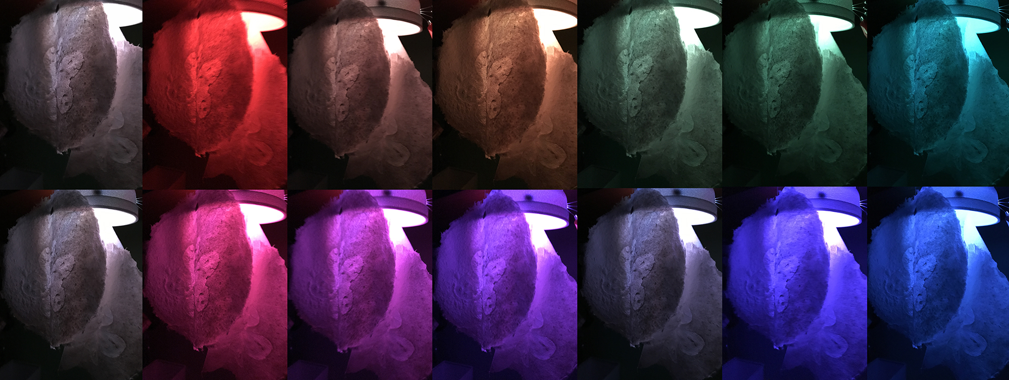
The image below shows the variation in the color of the object step by step, even though the control is continous, because it is an analogical reading (potentiometer), but the images was taken as a sequence to show the incredible possibilities.
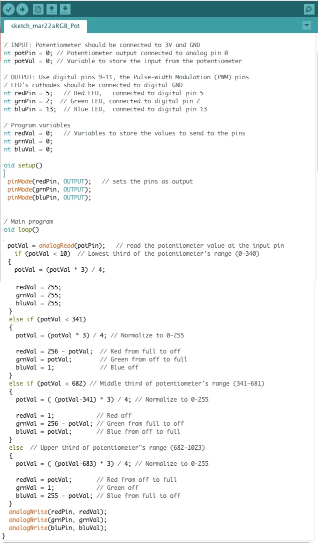
Here is the final code to this arduino control.
This code was Hacked and modify for my needs from Clay Shirky from NYU .
Link to the Final Code: https://drive.google.com/open?id=1e4FXVKXIILzZ7EY-xetenj8jR9F3tYJR
Finally the video with this interaction on the color light of the art object.
Apart of the experiments related here, I have also done many others researching and constructing sensores, and also interative objects that are documented in the weekly assignment from Week 05, even though I've made many of them after that.
The interactive Cap, that I've presented in this calss review I thought that had more relation to the Classe from Week 05, because of the sensor production.
But I reserved one special material for documenting here, that is the Grafeno's research I've done because this week is more related to technology and innovation.
Grafeno Thread
I decided to study a little bit about Grafeno, because it is a very special material and we think it will be the future of many electronic projects. So here I will describe only the Grafeno thread production and testing.
01. I've got a small amount of Grafeno to make these tests, so first of all I dispersed the Grafeno powder, that is very very thin, in a small bottle of white, water based, ink.
I've said dispersion, because the powder only disperse, not dissolve, neither dilute, in this case and many others, it is very important to use the correct chemical therms. This process has to be made very carefully, and gently, because Grafeno is very thin , as I've already said. Also very important, to use, gloves and mask to deal with Grafeno, because, there is still no enough studies about its toxicity, and colateral effects to health.
02. After dispersing, and homogenizing very well the Grafeno powder in the ink, I introduced one piece of cotton thread, and imbibed with the Grafeno paste, using the fingers , with gloves, to be sure that all the thread would be very well involved with the Grafeno mass.
03. I've done this process until the multimeter has accused the passage of electric current trough the thread.
04. After drying I used this thread as a connective thread to close the circuit, as a pressor sensor, to turn on the lEd light installed in the Handmade paper, as I've done and described in the week 05.
Week 05. E-textiles and Wearables
Here is the final result of this interesting experiment.
Please to check all I've done in the electronic field consult the weeks 05, 11 and the final project.
